|
Words and Pictures: Rob Bell |
|
|
K-series Cam Shaft Timing
|
Without doubt, one of the easiest and cost-effective
 ways of
extracting meaningful power from your MG's engine is to fit more aggressive cams
that those fitted to the engine when it left the factory. If you're also
planning cylinder head modifications, than a cam swap becomes almost mandatory.
A small selection of the cam profiles available are shown in the comparison
chart opposite (for more extensive lists of what is available, visit the Piper
and Kent cam web pages).
ways of
extracting meaningful power from your MG's engine is to fit more aggressive cams
that those fitted to the engine when it left the factory. If you're also
planning cylinder head modifications, than a cam swap becomes almost mandatory.
A small selection of the cam profiles available are shown in the comparison
chart opposite (for more extensive lists of what is available, visit the Piper
and Kent cam web pages).
It is possible to install any one of these cams using the existing, standard cam wheels - and you may be tempted to do so, given the that the Piper cam verniers cost a startling 80 quid each - and of course, you'll need two... But to do so would be a false economy; getting the cam timing correct with these pulleys will prove to be an almost impossible task. A classic example of this problem is the VHPD engine, as found fitted to MGF Cup, Lotus 340R and Exige. These engines use pretty warm cams as standard - as you'd expect for an engine with a reputed 190bhp performance. However, the engine was specified with standard, non-adjustable cam-pulleys - and the reality is that many of these engines do not make more than 177bhp. Where's the power been lost? Most likely, poor cam timing. Timing of these engines could be woeful - and recognising this as a problem on the high-performance derivatives of the Elise platform prompted Lotus to release a 'drivability kit' comprising a replacement inlet cam pulley with an offset locator dowel that altered the cam position by around 4 degrees. These pulleys remain available, and show significant benefits on these VHPD engines. Curiously, many report subjective "power" improvements by fitting these to more mundane K-series engines - but I've not seen definitive power plots to prove whether this is in fact the case - but perhaps alludes to some potential cam timing errors even on standard engines.
Getting the timing right can be the difference between a gutless engine that produces all its power in the top 2000rpm to a far more pleasant and tractable motor with good torque and excellent power throughout the rev range. Cam timing can make a huge difference to the characteristics of engine performance.
What is Cam Timing?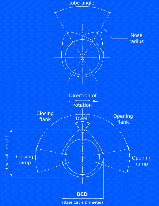
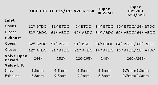
As you know, practically all car engines are four-stroke (intake, compression, ignition [power], exhaust), defined by the position of the cylinder - the Rover K-series is certainly no exception. When the cylinder reaches the absolute top of its up/down movement, it is said to be at Top Dead Centre (TDC). The cylinder moves through two complete up/down cycles for each complete power cycle (4-stroke: 2 up, 2 down). All timings refer to TDC position in relation to the end of the exhaust stroke of the cylinder. This applies to ignition (spark) firing as much as it does to cam timing. If the valve were to start to open 12 degrees before TDC (cam starting on the opening ramp of its profile - shown opposite, right), then this is recorded as 12 degrees BTDC (see above table, column one). The other cam timing point recorded in the chart above relates to bottom dead centre (BDC) - but for the practical purposes of this article is not used in the timing of cams.
It is important to remember that the cams do not rotate at the same speed as the crankshaft. For every two revolutions of the crank, the camshafts only rotate the once - they're down-geared by a ratio of 2:1.
The inlet cam, as its name aptly suggests, is the cam that opens the inlet valves, thus allowing the engine to draw in air and fuel for combustion. Typically, inlet cams open towards the end of the exhaust stroke (the overlap period where both inlet and exhaust cams may be open at the same time). This certainly applies to the standard and performance cams mentioned above - although the higher-power cams open considerably earlier (Piper BP270H for example - 20 degrees BTDC versus 12 degrees BTDC for the standard cam). Similarly, the inlet closes rather later on the hotter cams too - giving them much longer duration than the standard items.
The exhaust cam unsurprisingly relates to the cam working the exhaust valves. The opening timing of these cams relates to the BDC at the start of the exhaust extraction phase, and closes at some time after TDC. Comparing MGF cams, the standard MGF 1.8i cam profiles provide 24 degrees of inlet and exhaust cam overlap, where both inlet and exhaust valves are open at the same time at around TDC at the end of the exhaust stroke/ beginning of the induction stroke. This compares with up to 44 degrees of overlap with BP270H performance cams. A degree of overlap is good for performance - although the reason for this may not be immediately apparent. Remember that air has mass and inertia. Exhaust gases rushing out through the exhaust ports and out via the exhaust manifold causes a negative pressure wave to form in the combustion chamber that can be used to actively suck in fresh fuel and air through the inlet tract and into the combustion chamber - benefiting power.
It is worth pointing out that all valves are closed during the compression and ignition stroke - meaning that the cams have no additional height over their base circle diameter for around 50% of their circumference - providing the cam with its characteristic eccentric appearance (shown in the blue print figure opposite, above).
The time at which cams open, and how much overlap between inlet and exhaust cams, have a significant impact upon how the engine will perform. Open the inlet valves too late through incorrect timing, and you'll loose a significant opportunity to draw air and fuel into the engine, a problem that becomes progressively more acute with higher rpm. Moreover, with too much overlap, you may only succeed in venting that much needed oxygen and fuel straight out of the exhaust ports.
Getting the valve timing right is, therefore, extremely important.
Given that both inlet and exhaust cams are open at TDC means that this is a useful point at which to time the cams - so long as you know what the expected valve lift is for a particular cam profile (Dave Andrews has been an invaluable source of such information, and is able to supply a wide range of cams - but other cam suppliers should also be able to provide you with all the necessary information you require).
How are cams timed?
 On a practical level, there are effectively two ways of
altering cam timing on a K-series. One is to use offset dowels (Dave Andrews
makes these, and enables the standard cam pulleys to be offset from their
standard positions by up to 3-4 degrees - about 1/2 a tooth movement over the
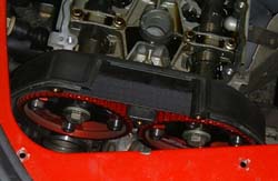
cam pulley). The other method is to use Vernier pulleys. A pair of
Vernier Pulleys can be seen pictured here (opposite), in situ in Tim Woolcott's
car - and neatly shows one of the unique differences between cam timing on an
MGF to almost any other vehicle equipped with a K-series engine: lack of access
space.
On a practical level, there are effectively two ways of
altering cam timing on a K-series. One is to use offset dowels (Dave Andrews
makes these, and enables the standard cam pulleys to be offset from their
standard positions by up to 3-4 degrees - about 1/2 a tooth movement over the
cam pulley). The other method is to use Vernier pulleys. A pair of
Vernier Pulleys can be seen pictured here (opposite), in situ in Tim Woolcott's
car - and neatly shows one of the unique differences between cam timing on an
MGF to almost any other vehicle equipped with a K-series engine: lack of access
space.
Vernier Pulleys are constructed in two parts: the centre spindle that bolts to the end of the cams themselves, and a floating toothed pulley that bolts to the centre spindle via slotted holes. This enables the outer pulley to be rotated independently of the centre spindle - allowing the cams to be timed independently of the position of the pulley on the toothed belt. This enables far greater precision in terms of cam timing than can possibly be achieved using the standard parts. Equally, there is infinitely more ways of getting things wrong if you're not careful enough...
The purpose of this article therefore is to go through the basic timing procedure, and illustrate some hints and tips passed on from both Dave Andrews and Tim Woolcott - Tim has gained quite a considerable amount of experience of setting cam timing on his MGF over the last couple of years - experience that will prove invaluable as we tackle a presumed cam timing problem on Steve Ratledge's MGF...
Equipment needed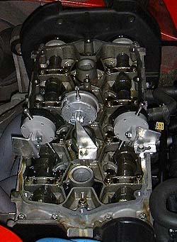
In order to use the DPIs, you will need to make some brackets and some extensions to the instrument's nose in order to determine cylinder height and valve depression. On the right is pictured the bracket arrangement used by Dave Andrews. Obviously, there is more than one way to skin a cat, and you can be quite creative with your own solution to this problem - but clearly, you can't rely on magnetic clamps - the engine is completely made of aluminium alloy and there is no flat steel in realistic proximity. The design features to be wary of is the need for the brackets to be torsionally stiff: if the brackets twist in use, you will not get either an accurate cylinder position determination nor valve lift measurement. The other design criteria is the angle of the valves. On a 1.8i head, this is 23 degrees from the vertical.
For the DPI extensions, the ideal solution is to tap a suitable length of metal dowel and screw this into the nose of the instrument. Easier said than done - the threads on the gauges I had access to were not the usual standard, commonly available die sizes, and were, moreover, subtly different on the instruments purchased from different suppliers - Draper's were threaded with an M2.7 die, whereas the pair of unbranded DPIs had a M2.6 thread... an easier option for many may be to carefully drill out the existing thread and re-tap to M3 - a die and tap size commonly and cheaply available (even my cheap Halfords set had this included).
 More on our home-made instrument
rig here.
More on our home-made instrument
rig here.
The assembly was fabricated out of materials and sundries that can be purchased from your local DIY store or Halfords.
Picture shows the DPIs assembled on top of a 'spare'
cylinder head I happened to have kicking around in the garage. As you do...
Time required
This job is far easier if you have some help on the day - and easier still if one of you is as experienced as Dave or Tim at performing this kind of work! Making your own brackets from scratch can take half a day. Timing the cams themselves will then take about half to a full day's work, depending on the amount of 'fiddle time' required. Once mastered, timing the cams can take under half an hour...
Instructions
|
1 |
 The
first step is to prepare your work area. As you can see, we chose the ideal
day in December to be working on a car outside... The
first step is to prepare your work area. As you can see, we chose the ideal
day in December to be working on a car outside...(Yes, that is melting snow on the gazebo... brrr!) |
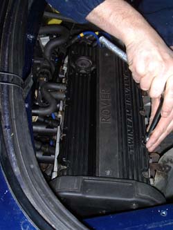
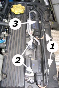
| 2 |
 Next, strip
down the rear deck and remove the engine access panel, as detailed in more
detail here. Next, strip
down the rear deck and remove the engine access panel, as detailed in more
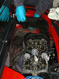
detail here.This gives you an excellent view of the cam cover, and ultimately excellent access to the top of the cylinder head. |
| 3 |
 Now
we can start to remove the cam cover bolts. These are 8mm headed bolts, of
which 10 are visible at this stage. Store the removed bolts in a safe
place. Now
we can start to remove the cam cover bolts. These are 8mm headed bolts, of
which 10 are visible at this stage. Store the removed bolts in a safe
place. |
| 4 |
 The
cam cover won't come off just yet - there are some hidden bolts. To gain
access to these, remove the plastic trim cover over the ignition leads and
spark plugs (later, post 2001 cars have a different cam cover and a
different ignition arrangement - disassembly is therefore a little
different, but the ultimate goal is the same - to remove the cover. See
additional step, 4a, below. The
cam cover won't come off just yet - there are some hidden bolts. To gain
access to these, remove the plastic trim cover over the ignition leads and
spark plugs (later, post 2001 cars have a different cam cover and a
different ignition arrangement - disassembly is therefore a little
different, but the ultimate goal is the same - to remove the cover. See
additional step, 4a, below. |
| 4a |
 Post
2001 (EU3 compliant) engines use a wasted spark ignition system and a
camshaft position sensor (CMP) to determine when to fire the spark
plugs, thus discarding the need for the distributor. The additional
components - two coil packs and the CMP - have to be disconnected/removed
before the cam cover can be lifted from the engine - where after the same
removal procedure detailed below applies to these cam covers once these
following three steps have been performed: Post
2001 (EU3 compliant) engines use a wasted spark ignition system and a
camshaft position sensor (CMP) to determine when to fire the spark
plugs, thus discarding the need for the distributor. The additional
components - two coil packs and the CMP - have to be disconnected/removed
before the cam cover can be lifted from the engine - where after the same
removal procedure detailed below applies to these cam covers once these
following three steps have been performed:
Now continue with disassembly from step 6. |
| 5 |
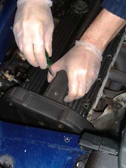
 Now
we need to remove those ignition leads (these are 8mm Magnecore leads -
yours may appear a little different). Now
we need to remove those ignition leads (these are 8mm Magnecore leads -
yours may appear a little different).Removal is very easy - the spark plug covers simply pop off. Remove cylinder 1 lead first (closest to us in this image's perspective) and work backwards. Be sure not to loose the two wire guides in the head. These are made of rubber and are simply slotted into the ignition gulley of the cam cover. |
| 6 |
 Tuck
the HT cables safely to one side. Now remove one of the spark plugs. I made
the DPI rig to fit over cylinder 4, so unsurprisingly we removed spark plug
#4. More on spark plug removal
here. Tuck
the HT cables safely to one side. Now remove one of the spark plugs. I made
the DPI rig to fit over cylinder 4, so unsurprisingly we removed spark plug
#4. More on spark plug removal
here. |
| 7 |
 Now
the remaining 5 cam cover bolts can be removed. Now
the remaining 5 cam cover bolts can be removed.
Next remove the breather pipes connected to the rear edge of the cam cover (between the cylinder head and inlet manifold - the 'S'-shaped pipe visible near the centre of the image opposite - there are also two breather pipes to diconnect on EU3 heads). |
| 8 |
 The
cam cover can now be removed. Tim's tip is to keep the cam cover gasket
together with the cover, and replace all the bolts in their respective holes.
Put cover in a safe place, on top of a sheet of news paper to keep the
assembly clear of dust and debris. The
cam cover can now be removed. Tim's tip is to keep the cam cover gasket
together with the cover, and replace all the bolts in their respective holes.
Put cover in a safe place, on top of a sheet of news paper to keep the
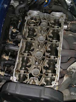
assembly clear of dust and debris.The cam ladder is now exposed. You can see the exhaust cam on the right of the picture (closest to the exhaust manifold) and the inlet cam on the left (inlet manifold to the left of picture). |
| 9 |
 Now remove the
driver's (RHS)
rear wheel - jack up the rear of the car, and support using axle stands.
This is vital, as it is inevitable that you will be leaning over the side of
the car, and for your safety's sake, it is essential that the car is stable. Now remove the
driver's (RHS)
rear wheel - jack up the rear of the car, and support using axle stands.
This is vital, as it is inevitable that you will be leaning over the side of
the car, and for your safety's sake, it is essential that the car is stable. |
| 10 |
 With
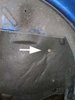
the road wheel removed, locate the fibreboard cover inside the wheel arch.
It is typically located and secured with a self-tapping screw. With
the road wheel removed, locate the fibreboard cover inside the wheel arch.
It is typically located and secured with a self-tapping screw.
If the cover has not been removed for a while, then there is a very good chance that the self-tapper will have corroded into the aluminium engine cradle. You may need to drill the screw out to remove... An unpleasant complication of what should be an otherwise straightforward job! |
| 11 |
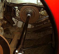 With cover removed, you now
have ready access to the crank pulley. The crank pulley is pictured here,
with the socket and extension slotted onto the crank pulley bolt - which is
the mechanism by which we will be turning the engine over for when we start
to measure and ultimately alter the cam timing. With cover removed, you now
have ready access to the crank pulley. The crank pulley is pictured here,
with the socket and extension slotted onto the crank pulley bolt - which is
the mechanism by which we will be turning the engine over for when we start
to measure and ultimately alter the cam timing.The eagle eyed readers will have spotted that the MG has changed colour! This picture was actually taken of Tim's car when under going similar treatment to Steve's... |
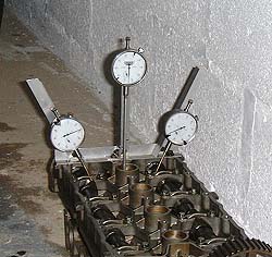
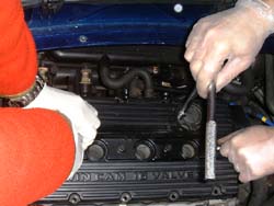
| 12 |
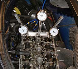 Returning
stop side now, it is time to install the dial position instruments - here's
our timing rig in situ on Steve's engine. Returning
stop side now, it is time to install the dial position instruments - here's
our timing rig in situ on Steve's engine.You'll note three dials: left hand dial is used to measure depression of the inlet tappet (giving us a measurement of the inlet cam lobe lift); the right hand dial is measuring a similar parameter, but this time for the exhaust cam. The high-mounted centre dial is to enable determination of TDC. The dial is mounted high as this helps a single operator determine TDC whilst also cranking over the engine via the crank pulley bolt in the wheel arch - saves on a degree of neck stretching! Unfortunately, the dial does not have sufficient travel to measure both TDC and BDC - but this is not a problem as we are measuring and timing the cams at TDC only. |
| 13 |
 Whilst I
was attaching the measurement rig, Steve and Tim were busy removing the cam
cover - this is the next step. I don't have a photo from Steve's car, but
here's one I took earlier (in true Blue Peter style) of Tim's car whilst at
Dave Andrews' emporium. Whilst I
was attaching the measurement rig, Steve and Tim were busy removing the cam
cover - this is the next step. I don't have a photo from Steve's car, but
here's one I took earlier (in true Blue Peter style) of Tim's car whilst at
Dave Andrews' emporium.
There are five retaining bolts to be removed. The lower most, sixth one does not need removing completely, as the cam cover is slotted. This bolt merely needs to be loosened, and the cover pulled upwards to be removed - as shown opposite. |
| 14 | Now we are at a stage whereby
we can starting thinking about measuring the current cam timing (probably an
excellent opportunity for a cup of well-earned tea too!) We took a tea-break
just to get warmed up, and ensure that we had the correct measurements ready
to time the inlet and exhaust cams. Steve had a pair of Piper 633 cams on his engine, which were fitted a by a well known MG specialist. However, cam timing is not their speciality (which they freely admit), and Steve felt that the car wasn't running as well as expected. Incorrect cam timing was suspected. Dave Andrews recommends a lift on the inlet and exhaust valves, at TDC, of 45 and 30 thousandth of an inch respectively. In metric, that converts to 1.14 and 0.76 millimetres - which is the unit of measurement on our DPI gauges. Let the timing begin! |
| 15 |
The first
step now is to rotate the crank to determine TDC. Attach socket (17mm), with
long extension to your power bar (long, long lever for your socket set!) and
rotate the crank. At this stage it doesn't matter all that much which
direction you rotate the crank - you will get to TDC eventually! As mentioned earlier, we are measuring TDC at the end of the exhaust stroke - a time during which both inlet and exhaust cams are lifting the valves - so look for this too (indicated by movement on the gauges). TDC is readily identified - you will find that the dial comes to a halt and then rapidly reverses direction once TDC has been reached and passed. Rewind slightly to find that high point. Fortunately, the cylinder doesn't have much of a dwell period at TDC, so once found, it is easily repeated with reasonable accuracy. Once you are happy you've found TDC, rotate the DPI gauge's face so that the needle now is pointing to 'zero'. |
| 16 |
We've
now found TDC, but at this stage, the readings on the inlet and exhaust
gauges are reading random numbers - the next stage is to determine the point
of zero lift when the cam is at its base circle diameter - see blue-print
figure above for explanation of this term. Do this for the inlet and exhaust
valves individually - there is too much to look at and double check to do
them both together. |
| 17 | Whether looking at the inlet
or exhaust cam, the procedure is the same: wind the crank so that the cam's
lobe moves off the tappet underneath. Once the needle stops moving, then
assuming that the gauge's feeler arm hasn't fouled the head casting, then
you've reached the cam's base circle diameter (zero lift). Set the dial face
so the needle reads zero. Now rotate the crank so that the cam lobe once again comes to bear on the tappet. It is nice, but not essential, to measure the maximum lift of the cam to ensure that your DPI is showing that maximum lift is the same as the maximum lift of the cam, as specified by the manufacturer. Move the crank slowly: the cam will develop a considerable amount of lift very quickly: the dial moves one complete revolution for every millimetre of lift - and as the needle swirls round, it can be almost impossible for an observer to keep count!!! 633 cams have 10mm of lift: thankfully on Steve's car, we measured 10mm on both inlet and exhaust cams, as we'd expect. Now wind the cams back to the base circle, and zero lift to ensure that the DPI re-zeros correctly. |
| 18 | Now rotate the crank so that
the cam lobe once again starts to bear upon the tappet. This is where having
someone to help you comes in handy: as you check to see when TDC arrives on
the centre gauge, someone else can look to see how the cam dial is moving.
Once you've brought the piston back to TDC, make a note of the cam dial gauge reading. Then wind back the crank so that the cam returns to its base centre to confirm that the dial gauge returns to zero lift. If it does, then you can be reasonably confident of the reading. Now repeat for the other cam. |
| 19 | Now compare your measurements
to the recommended lift at TDC for the cams you've got fitted. We found that
on Steve's car, the inlet was reading 1.84mm and the exhaust 1.38mm
respectively - 0.70 and 0.64mm more lift than Dave recommends for the 633
cams fitted. Having determined that the timing is not correct, now we have to go about correcting the error. |
| 20 |
 As
with measuring cam lift, the procedure for inlet and exhaust cam timing
corrections is essentially the same - but do each individually. As
with measuring cam lift, the procedure for inlet and exhaust cam timing
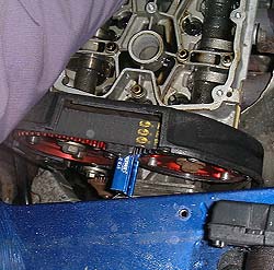
corrections is essentially the same - but do each individually.The first step is to bring the cam onto its opening ramp - it actually isn't too critical as to where exactly it is, so long as it is somewhere in the middle of the lift flank (see blue print figure above for explanation of lift flank). Once the cam is in the right position, lock the two cams together using the cam pulley locking tool, as pictured opposite, right. It's the blue anodized alloy thing wedged between the two anodised red cam pulleys in the centre of the picture. The outer part of the Vernier pulley can now not move. |
| 21 |
 With
the outer part of the pulley locked into position, we can now start to think
about moving the cam relative to the timing belt. To do this we need to undo
the lock-bolts in their slotted holes so that the pulley spindle can be
moved independently of the outer toothed part of the pulley. The lock-bolts
on Piper pulleys have Allen-heads, so a suitable Allen key (or Allen key on
a socket attachment - which might be easier here given the space
limitation) needs to be used to release (but not remove!) the lock nuts (4
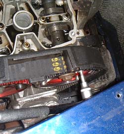
on older pulleys, three on the newer versions). With
the outer part of the pulley locked into position, we can now start to think
about moving the cam relative to the timing belt. To do this we need to undo
the lock-bolts in their slotted holes so that the pulley spindle can be
moved independently of the outer toothed part of the pulley. The lock-bolts
on Piper pulleys have Allen-heads, so a suitable Allen key (or Allen key on
a socket attachment - which might be easier here given the space
limitation) needs to be used to release (but not remove!) the lock nuts (4
on older pulleys, three on the newer versions).The picture opposite shows the Allen key socket in position for illustration purposes - the cam pulley locking tool is not in position for this picture. |
| 22 |
 Once the two
halves of the pulley have been released, the cam can be rotated. As seen in
this image, the cam has a socking great bolt on the end of it (17mm). We can
put a socket and ratchet on this to rotate the whole cam to either add or
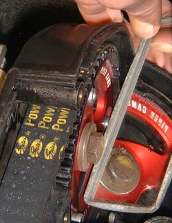
remove lift. Once the two
halves of the pulley have been released, the cam can be rotated. As seen in
this image, the cam has a socking great bolt on the end of it (17mm). We can
put a socket and ratchet on this to rotate the whole cam to either add or
remove lift.Before we do this, set the cam DPI dial face so the needle points to zero. Now we can move the cam to either add or remove lift according to the difference in lift at TDC between desired specification and measured. In our case, the difference was about 0.6-0.7mm excess lift for both inlet and exhaust cams - so we needed to remove some lift from both to get the desired specification. To do this, the cam was rotated so that the cam lobe was slowly moved off the tappet face - again, it is helpful to have someone else there to read off the dial as you slowly move the cam (this can be hard work because you may be working against the valve springs). Once the dial gauge is reading the desired value of alteration, nip the pulley lock bolts back up so that the pulley effectively becomes as one once again. Sanity check time: remove the cam pulley locking tool, wind the crank so that the cam returns to its base centre diameter, and re-zero the cam gauge face so the needle is showing zero lift. Now rotate the crank so that the piston reaches TDC - and measure the lift of the cam - hopefully it now reads the desired lift. If not, you will have to return to step 20, and repeat - this time comparing the current lift at TDC with the desired measurement. |
| 23 | Once you've done this with
both cams (if necessary), it is time for another sanity check - just to make
sure that both the inlet and exhaust cams are now showing the correct lift
at TDC. Once you've done this, you can reassemble the engine - hurrah! A very useful Dave Andrews' tip here is "mark the Verniers carefully first so it is easy to go back [to the original cam timing] without using the gauges. It might be worth marking both settings so you can easily alter them on the RR day and see the results, if the Verniers are marked you don't need the gauges..." Dave uses a scribe or scalpel blade to mark the inner and outer parts of the pulley - the thin marking you get makes it easier for accurate re-alignment. Naturally, the reassembly process is performed in true Haynes manual tradition: the reverse of the disassembly instructions. Don't bother putting the road wheels on just yet, or replacing any of the covers (excepting the cam cover) - just in case you need to get back in there to perform any corrections (shouldn't be necessary if you've checked and double checked all your measurements). First safety check is to turn over the engine by hand, listening carefully to ensure that there isn't any tell-tale sound of valve hitting piston 'click' - if there is, stop, go back and check the cam lifts from scratch. Now, having checked that the gearbox is in neutral, you can start the engine. Listen carefully: if there is any kind of metallic clicking you've made a serious boo-boo with your timing: stop the engine immediately before the repair bill becomes stratospheric! Much more likely is that the idle is even and all is well - stop the engine and complete the reassembly process. |
| 24 | The sternest test yet: go out
for a drive to see whether the changes made to the cam timing have made the
desired difference. Steve was a very happy bunny - so job was a good 'un -
and definitely worth spending the morning in the worst that the British
winter weather could throw at us... Time for
another cup of tea... |