Hydragas
Links on this page: What
is Hydragas/ History/
How does it work/
Problems
External links on this site: How to
lower/raise Hydragas suspension/
Service/repair the Hydragas Sphere

|
|
Hydragas |
|
|
|
One of the many technical highlights of the MGF at its 1995 Geneva launch was its suspension, using Alex Moulton's innovative Hydragas suspension system that had been previously utilised to good effect in many other British Leyland vehicles previously. It is this gas/interconnected fluid system that imbues the F with its superb ride and handling characteristics - but can, due to fluctuations in ride height, be the source of some of the tracking related problems highlighted elsewhere within this micro-site.
Hydragas is a fluid/ gas based suspension system that is an alternative to conventional springs and dampers - although on the MGF, auxiliary dampers are actually employed to further tune the sports car characteristics. In one respect, it can be regarded as being similar to Citroen's hydraulic suspension that remains in use on some of Citroen's products to this day; a fluid-linked suspension system with hydraulic links present between individual springing units. Unlike Citroen's suspension however, the Hydragas system does not rely on engine linked hydraulic compressors: all the suspension pressure is contained within pre-pressurised fluid/ gas spheres.
In operation, Hydragas uses a capsule of nitrogen (the
"nitrogen egg"), as its springing medium - as gas, unlike fluid, is
compressible. The fluid in the system, compressed by the movement of the
suspension compresses the 'springy' nitrogen egg and also displaces some fluid
to the interconnected suspension unit on the same side of the vehicle. Internal
valves that restrict flow of fluid within the suspension unit provides the
damping properties. The operation of Hydragas is discussed in some more detail
below.
 The Mk1 Austin Mini. For a few short years, the Mini gained this superb suspension system to quell the bounciness that ruined the ride. However some felt that this robbed the car of some of its enthusiast appeal, and the Mini reverted to solid rubber cones in later iterations of the car. Pity, IMO. |
Hydragas is not a new suspension system. It was originally found on BMC small car products of the early 1960s (including the Mk1 Mini, as pictured opposite). This system's earlier guise was known as Hydralastic. Highly lauded at the time, this ingenious system imbued 'big car' suspension feel and comfort to a short wheel base vehicle.
Hydralastic evolved into Hydragas for the 1970s Austin Allegro. The inherent damping characteristics of these spheres means that cars fitted with this system do not necessarily require additional conventional dampers. Not that Hydragas was restricted to small cars: it was also found on a range of other Austin products throughout the 70s and 80s, including the Maxi, Princess and Ambassador.
Were it not for one car, the Hydragas system would have died with the Austin Allegro in the early eighties. That car was the Austin Mini Metro (subsequently evolving into the Rover Metro/100).
 The Hydragas sphere: actually two spheres in one! See below. |
When the MGF concept was being developed, in the interests of saving costs a requirement was that Rover use existing parts from their passenger car range. Rover engineers eventually elected to utilise the K-series powered Rover Metro/100 front sub-frame both at the front and at the rear of the car. Through some clever development, the front subframe was used to carry the front suspension and steering gear as it was designed to (albeit without having to carry the engine!), whilst the adapted rear-mounted subframe carried the now mid mounted K-series engine, suspension (now modified for its use at the rear of the car) and drive train. The use of the Metro sub-frame inevitably brought with it that car’s Hydragas suspension and the Metro’s unequal length double wishbone suspension geometry front and rear (the now un-used Metro rear subframe is a semi-trailing arm affair, near identical to that found on the Mini). Double wishbone suspension, as we all know, is ideal for a sports car, with the systems excellent camber angle control - albeit at the expense of some wheel travel (not the be all and end all for a sports car!). Because of the Sporting nature of the F, the Hydragas system was augmented with conventional dampers for further improved suspension control, whilst maintaining compliant springing (very much in the Lotus school of thought!).
This intelligent use of existing technologies
brought us the MGF at a far lower cost than developing all-new sub-frames from scratch.
The affordable MG sports car lived again!
How does Hydras suspension work?
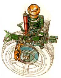
 Figure 1: the Hydragas sphere. The sphere has two main compartments: a nitrogen gas 'pocket' (pale blue, above) which is separated from the fluid compartment (green). The fluid compartment is divided into two; fluid movement between the two halves is restricted by a 'damper valve' - the properties of which dictate spring and damper rates. When the suspension moves up or down, the tapered skirt, or suspension cone, displaces fluid that is either pumped to the rear suspension, or is passed through the damper valve to the sphere. |
Hydragas suspension consists of four spheres - one at each wheel. In the case of the MGF, two pairs of spheres on each side of the vehicle are interconnected, front to rear.
The interconnection is a hydraulic link, with a water/ rust inhibitor/ antifreeze mixture acting as the media. It's the antifreeze that gives the Hydragas fluid's characteristic fluorescent green appearance.
The Hydragas sphere
Each Hydragas 'sphere' is actually two interconnected spheres siamesed together. The upper sphere contains a rubber diaphragm 'separator' that separates two compartments: one containing nitrogen gas and the other, fluid. It is the nitrogen gas in the upper sphere that performs the majority of the springing function.
Gas, being compressible, compresses when the pressure inside the Hydragas unit goes up, as occurs when the suspension is in jounce. It will then tend to want to expand back to it's original volume once the pressure inside the spheres diminishes. If you were to increase the pressure of nitrogen in the sphere, the "spring" would effectively become stiffer and likewise, if the pressure were reduced, the spring rate dropped. As gas pressure is linked to the fluid pressure, some degree of spring rate control is achievable through Hydragas fluid pressurisation, although other approaches include altering the gas pressure itself (see the DPR Racing web page for more details)
The Hydragas fluid in the upper sphere communicates with the lower sphere via a 'damper valve' that controls the rate at which the fluid can enter or exit the upper sphere, and thus has a critical impact upon both springing and damping.
The lower sphere also contains a rubber diaphragm - but this time, it separates the fluid containing compartment from the outside world. Bearing against this rubber diaphragm is a metal cone (also known as a 'displacement cone' or 'trumpet').
The Displacement Cone
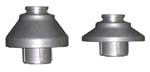
This metal cone has an important role to play: it's shape
will dictate the spring rate by virtue of the volume of fluid that is shifted
for any given suspension movement up or down. In the picture shown left, the
cone on the right will result in a much larger fluid displacement for any given
movement in the suspension. As a consequence, the Hydragas 'spring' will be much
much stiffer than the cone shown on the left. Clearly this example is
exaggerated, but a there are differences in the shape of the taper skirt cones
found fitted to the front and rear suspension on the standard MGF.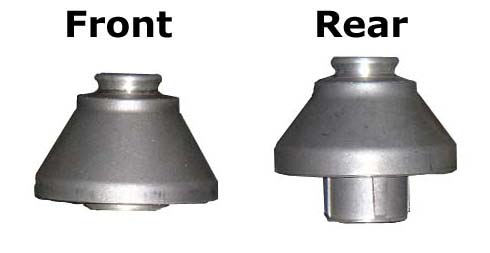
The example shown here on the right are the cones found fitted on the MGF Trophy 160. Study the cone designs carefully, and you'll note two things. Firstly, there is a clear difference in height between the front and rear cones (the rear being longer). Secondly, if you compare the angle of the cones, there is evidence that one cone is more acute than the other. All other things being equal, this would equate to one pair of springs being stiffer than the other: in this case, the rear springs are stiffer (reflecting the MGF's weight distribution).
Since we are discussing the tapered skirt, it makes sense to quickly mention the suspension components that are acting upon it - in this case the suspension link also known as a 'suspension knuckle'.
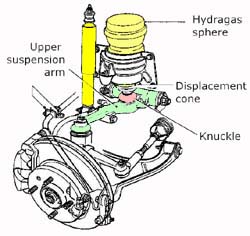
The suspension 'Knuckle'
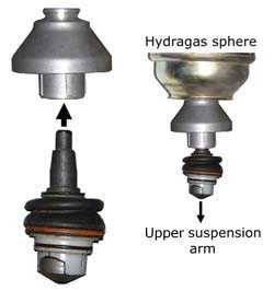
The suspension knuckle is a vertical link that transmits the suspension load and movement upward into the Hydragas sphere, and the reactive force from the sphere back down into the road. As shown in the picture montage opposite, the knuckle fits into the displacement cone, which in turn slots into the Hydragas sphere (via its tapered skirt) to bear against the lower sphere's rubber diaphragm [note that I have not included the return spring that sits over the knuckle, under the displacement cone for reasons of diagrammatic simplicity]. The complete front suspension assembly is shown in the line diagram below.
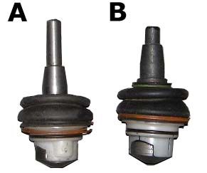
The Lowering Knuckle
The length of the suspension knuckle has a significant bearing upon the suspension ride height: the longer the knuckle, the higher the ride height, and therefore the shorter the knuckle, the lower the ride height. This principle forms a significant component of many a lowering kit - the 'lowering knuckle.' These kits are available from a number of MGF specialists, including those from Mike Satur and Brown and Gammons for example. But MG themselves have not been averse to this method of lowering, as the figure on the left indicates. Compared with the standard knuckle, A, it is clearly evident that the knuckle found fitted to the MGF Trophy 160, B, is a much shorter and as a result, the suspension is 10mm lower than the standard MGF.
If you are considering lowering your MGF, then installation of a shorter lowering knuckle is THE recommended course of action. The other method of lowering your MGF is discussed here.
Hydragas Interconnection
As mentioned earlier, the lower, fluid-filled sphere is interconnected with it's partner sphere on the same side of the car: the interconnection is from front to rear, and NOT from side to side.
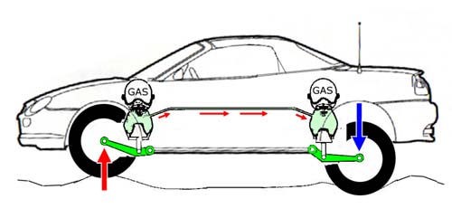
In the above diagram, one of the basic working principles of the Hydragas suspension is illustrated - namely, how the suspension is capable of imbuing a car with a short wheel base with such an excellent ride. Taking the above as an example, when the front wheel strikes a bump in the road, fluid is forced into one of two compartments (remember that fluid cannot be compressed). Either fluid will be pushed into the gas/fluid sphere on the top of each Hydragas unit, or it will be channelled to the rear Hydragas unit. The consequence of this interconnection is that as the front suspension is compressed upwards, the rear Hydragas unit is pressurised, forcing the rear wheel to the ground. The net result is that the pitching motion associated with a short wheel base car is counteracted by the reaction at the rear to what is happening at the front - and vice versa.
What is not relayed by the above diagram is another benefit of Hydragas: roll resistance. Because the suspension is interconnected, when the car rolls as it corners, both front and rear Hydragas spheres are pressurised such that fluid transfer between the spheres is negated. This means that more of the fluid movement has to be into the upper, gas/fluid sphere, resulting in what is effectively a higher gas/fluid pressure under roll than is present under bump. Net result: the suspension is stiffer in roll than it is in bump. Clever.
However, the interconnection is not all good news. Under acceleration/ deceleration, fluid will be shunted away from the direction of weight transfer that results in exaggerated rates of pitch under these circumstances. This has been at least partly compensated for on the MGF by the implementation of anti-squat geometry on both front and rear suspension set ups. The MGF Trophy takes this process one step further by using a flow restrictor in the for-aft interconnection pipe. The ultimate solution however, is the complete removal of the interconnection pipe - for this you need to go and visit Tech-speed (also available from other MGF specialists such as Motobuild) for their much vaunted 'Four Nipple Job' - a system that I think works superbly well.
Further reading:
Hydragas suspension is largely problem free after
three decades of development, but there some issues that directly relate to the
system’s application in the F.
The Metro Legacy
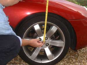
Remember that the MGF uses Metro sub-frames, and the Metro is a Super-Mini sized hatchback. The geometry and suspension pick points were therefore maximised for this application. Unfortunately for us, the Metro has a higher standard ride height than the F. For better handling, the F has been lowered by the Rover development team as far as can be achieved without unduly affecting camber. The ideal ride height is said to be 368mm, plus or minus 10mm (these measurements are made on the front wheels, from the centre of the wheel, to the wheel arch lip vertically above it at an ambient temperature of 17 Celsius - as pictured left). Lowering the ride height below the lower limit of this range can lead to unacceptable camber changes. [click here for an explanation of the camber problem]
Therefore it is critical that the suspension height is properly set before the car is put into daily service. Unfortunately, not all dealers have all the necessary equipment to perform a thorough geometry check correctly (a process that requires 4-wheel laser geometry checks), and the lowering process needs to be undertaken with much care, attention and patience- attributes that are under great threat under pressures of time and workload in a busy dealership workshop. The exacting standards that are required are evidenced in the Workshop manual, that states that the car should be allowed to settle for over an hour in a constant temperature environment (the figures below are for an ambient temperature of 17 Celsius) prior to any geometry checks. Then the car needs to be regularly ‘bounced’ gently at each corner to ensure that the equilibrium of the system is reached. The car's ride height can then be adjusted to 368mm ±10mm (measured from the centre of the wheel to the wheel arch vertically above- as mentioned above). Without sufficient care, the car can drop or rise further after suspension depressurisation or depressurisation respectively, and will throw out the tracking as a result.
Changes CAN be carried out successfully, but it is a process that takes time and patience. Read more here.
When the rubber fails...
 Vulcanised rubber does have a lifespan, although in my
experience with my 1967 Hydralastic suspended Mini, that lifespan can be
extremely long (which is terrific news, as in 2002 production of the
Dunlop-Moulton Hydragas sphere ceased - which means a finite number of
replacements from now on!). However, when it does fail, it can mean either
nitrogen gas escape, or loss of fluid. The solution in either case is
replacement, as repair is next to impossible. Dieter recalls his experiences
here and again
here, with
photographic evidence for the morbidly interested!
Vulcanised rubber does have a lifespan, although in my
experience with my 1967 Hydralastic suspended Mini, that lifespan can be
extremely long (which is terrific news, as in 2002 production of the
Dunlop-Moulton Hydragas sphere ceased - which means a finite number of
replacements from now on!). However, when it does fail, it can mean either
nitrogen gas escape, or loss of fluid. The solution in either case is
replacement, as repair is next to impossible. Dieter recalls his experiences
here and again
here, with
photographic evidence for the morbidly interested!
Curiously, when a Hydragas unit fails, it is typically the rear units that are the most vulnerable. An adequate explanation for this has not been found, although heat is one proposed factor (near the engine).
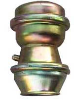
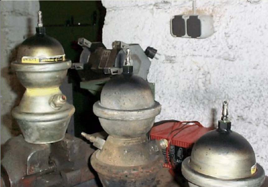
Read more here - it is possible to re-charge a nitrogen depleted Hydragas sphere - Alexander Boucke tells us how he and Alex Moulton came up with the method of adding a Schrader valve to re-charge the nitrogen egg (pictured opposite).