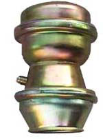
 |
Common problems: Hydragas de-pressurisation
low ride height and poor ride and
handling
|
Words: Alexander Boucke, Alex Moulton, Rob Bell
Pictures and figures: Alexander Boucke, Rob Bell |
|
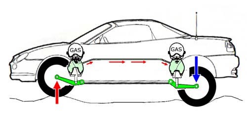 |
Figure 1
Hydragas suspension in an MGF – upward movement of the front suspension forces
fluid up towards the springing medium (the nitrogen egg) and also towards the
rear suspension, as each side is interconnected front to rear. The system
reduces pitch in a short wheel base car, and also resists roll well without
recourse to thick anti-roll bars. |
What is Hydragas?
Hydragas suspension was one of the technical high-lights of the MGF from launch
in 1995. Derived from the Rover Metro/ Rover 100, the MGF utilized this
incredibly compact suspension system that offers incredible pitch and roll
damping characteristics to provide a sports car package that was also capable of
handling the long-distance Gran Tourismo role with ease.
Hydragas consists of front to rear hydraulically interconnected suspension units
using nitrogen gas as their springing medium. With a Hydragas unit at each
wheel, suspension movement is transmitted to a displacer that moves
incompressible fluid both in the direction of the nitrogen ‘egg’ – a capsule of
gas encased within the alloy hydragas sphere and a rubber diaphragm – and to the
interconnected suspension unit at the other end of the car (figure 1).
Nitrogen, being a gas, is compressible – and this is what provides the springing
of the Hydragas unit. Damping is achieved through the fluid valve dividing the
displacer sphere from the fluid/gas divided nitrogen egg above it (figure 2).
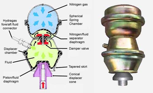 |
Figure 2
The Hydragas sphere explained: it consists of two spheres – the top containing
the nitrogen ‘egg’ – which performs the springing function, and a lower fluid
containing chamber (the displacer chamber) where the hydragas
fluid is either displaced through a 'damper' valve between the bottom and top
champers or to the other linked Hydragas sphere at the opposite end of the
car (as in figure 1). |
The main problem with Hydragas is that over time, the sealed units lose gas and
become less effective.
The analogy here is with the helium balloon you might buy for your children.
When new, it is fully inflated and under pressure. But a day or two down the
line, the balloon appears to deflate until one day, it is found lying limply in
a corner completely flat.
The balloon hasn’t punctured – and indeed you could
potentially re-inflate it if you were suitably inclined. The problem is that the
helium gas has simply diffused through the skin of the balloon.
A similar
process is at work with the Hydragas sphere – but in this case, nitrogen is the
gas, and it takes in excess of 15 years for a significant (i.e. noticeable)
amount of it to escape through diffusion from the well-designed Hydragas
nitrogen containment egg.
Alexander Boucke pioneered a method for recharging the Hydragas sphere – and
with Alexander’s permission and technical input from Dr Alex Moulton I have
up-dated his original article with particular reference to the MGF.
Typical Problems with Hydragas-Units
There are 3 basic problems occurring with the Hydragas suspension system that
leads to depressurization and loss of suspension/ride height.
Unfortunately, the most common is loss of the Hydragas fluid. Unfortunate
because the commonest mode of failure is due to rupture of the rubber outer
membrane for which there is no known repair and replacement is the necessary
recourse. It is easy to spot though: you’ll find a trickle of fluorescent green
fluid dripping from the suspect suspension unit. Failure of Hydragas units on
the MGF typically affect the rear units – and appears more common in parts of
the world where there are higher ambient temperatures and harsher road
conditions than are typically found in Northern Europe. A much rarer cause of
loss of Hydragas fluid is through failure of the interconnection pipe work, but
is worth investigating a sudden drop in suspension height affecting one side of
the car. It isn’t unheard of for the careless to place a jack under the
interconnection pipe causing it to split and fail… You can read more about the
fluid loss problems on Dieter’s web page
http://mgfcar.de/hydragas/blownhydra.html
The other two causes relate to loss of nitrogen gas pressure.
Loss of gas (1): the diaphragm separating the gas from the fluid is defective.
Due to the gas and the liquid mixing there is a (sudden?) drop in pressure, but
no fluid visibly escaping. Repair is not possible and replacement the only
recourse.
Loss of gas (2): a very common problem on older cars is the onset of very firm
or harsh suspension. The usual cause is the slow loss of gas due to slow
diffusion of nitrogen through different parts of the Hydragas displacer. This
cannot be avoided and shows in a car settling at a lower ride height evenly over
the years. Depending on how the car is used, these symptoms may not become
noticeable to the owner in the first 10-15 years, but will become the dominant
mode of hydragas failure in MGFs in the coming years, if the experience of
owners with older Hydragas-equipped cars (Allegro, Princess, Ambassador, Maxi,
Metro) is replicated in our MGs.
Nitrogen diffusion is insidious
You don’t go out one day and think: “Crikey! My MGF’s Hydragas has lost all of
its nitrogen!” Nitrogen loss is a slow and insidious process. Every few years,
owners will find that their car’s ride height has become a bit low and the ride
isn’t as good as it once was. On taking the car to a garage, the charge pressure
will have dropped considerably below the original 400psi (probably more in the
region of 300psi by the time the ride height [measured between the wheel centre
and the wheel arch lip vertically above] drops below 340mm). Initially,
resetting the ride-height to normal (measured at the front wheel: 368mm+/-10mm
at an ambient temperature of 17C) will help, but later, as nitrogen depletion
becomes more advanced, the car’s ride will get harsher the higher the vehicle
sits. When ride quality starts to become a problem, there will be practically no
nitrogen left in the upper sphere; the nitrogen volume now replaced with
hydragas fluid, and the Hydragas sphere will effectively have become
hydraulically locked with practically no suspension movement at all.
The latter problem was the affecting Alexander’s Hydragas-suspended Austin Maxis
so much, that he hardly used them; they had become too uncomfortable to drive.
This is when Alexander approached Dr. Moulton in search for a solution. Between
the two of them, they discussed the problem, leading to the solution described
in the following sections.
Ride-height and gas-pressure
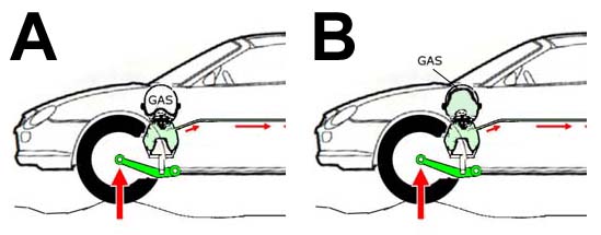 |
Figure 3
Progressive depletion of nitrogen gas means less available suspension movement
due to loss of the springing medium – meaning that for a given amount of
suspension movement, the suspension runs out of available ‘travel’ much sooner
(B) when compared to a suspension with the full compliment of gas (A). |
Looking at a Hydragas displacer the steel sphere sitting on the top of the unit
is most prominent. This contains the gas (Nitrogen) at the top end (the
“nitrogen egg”) and Hydrolastic-fluid (basically water and alcohol) at the lower
end separated by a flexible, rubber diaphragm.
We can regard the nitrogen egg as a nice, large nitrogen-filled cushion, which
absorbs the movement of the suspension in much the same way as a metal coil
spring. If there is plenty of nitrogen filling the sphere, the car will ride
softly, the large compressible cushion permitting plenty of wheel travel. On the
other extreme, if there is virtually no Nitrogen left, then the gas-cushion is
very shallow and not much wheel-travel is possible. The result of this is a
harsh ride – essentially the suspension media is ‘bottoming out’ over even very
modest road undulations (figure 3).
The second component affecting the volume of the gas-cushion inside the unit is
the line-pressure of the suspension fluid. Due to the conical shape of the
suspension displacement pistons acting on the Hydragas displacers, the pressure
exerted by suspension movement increases proportionately with linear deflection.
The higher the Hydragas line pressure (which will manifest by a higher ride
height), the greater the resistance to suspension movement – and hence a firmer
ride will result.
The pressure of the nitrogen gas cushion and that in the hydragas fluid line are
equal – and thus if hydragas fluid volume is increased to achieve a particular
pressure, the nitrogen gas cushion decreases proportionately, which in turn may
mean less available suspension movement. If hydragas fluid has to be pumped into
the system to compensate for lost nitrogen gas pressure and volume, nitrogen gas
pressure can be restored – but at the expense of the size (volume) of the
nitrogen gas cushion – and thus suspension movement. As the units become older,
with more advanced stages of nitrogen depletion, the amount of available
suspension increases until there is practically no movement left – at which
point the units are essentially hydraulically locked solid, and the car’s ride
consequently will feel extremely harsh. Interestingly, if the pressure is backed
off a little, the ride will feel a little softer, but with the problem that
there will be little in the way of suspension resistance to movement, and the
suspension will tend to bottom out.
As an aside, dropping an MGF with essentially normal nitrogen gas volume by
letting out Hydragas fluid for cosmetic reasons may be dangerous. Dropping ride
height in this way means reducing the pressure of the Hydragas circuit through
the removal fluid volume, and that in turn causes the nitrogen pocket to balloon
under the reduced pressure in the system, potentially blocking the openings of
the damper-unit inside the Hydragas displacer. Obstructing the damper valve in
this way can leave the car with somewhat unpredictable behaviour! If you want to
lower the ride height of an MGF, the preferred method remains the same – shorten
the length of the suspension knuckle.
How to repair/service Hydragas Displacers
To get old units back to proper working order Nitrogen cushion needs recharging.
The way that this can be achieved is through the fitment of a valve to the
nitrogen egg. The picture below shows 3 Austin Maxi Hydragas units ready to go
into a car again having been so modified (notice that their size and proportions
are somewhat different to those used on the smaller MGF and Metro).
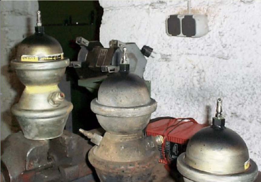 What is evident is all four units will need to be taken out of the car. [Picture,
opposite, three Austin Maxi Hydragas unuts - image
credit: Alexander Boucke]
Parts needed
For each displacer a Schrader-valve, just like the ones fitted to the
fluid-lines of Hydrolastic- and Hydragas-cars, is needed, together with a boss
into which it can be screwed. This boss needs to be of steel, so that it can be
welded onto the top of the nitrogen egg. Alexander found zink-plated reduction
pieces from 1/4in outer to 1/8in inner thread. After sawing off the 1/4in outer
thread they where well suited for the job.
Next you need to look out for a solution on how to re-charge the units with
Nitrogen, once everything is put together. As originally manufactured, Hydragas
units were charged with a 99% nitrogen, 1% SF6 (by volume) gas mixture. This
won’t be readily available to the home mechanic. However a viable alternative is
available from the tyre trade; many tyre fitting specialists sell 'tyre-gas' (or
whatever they call it) – and this is usually nitrogen. Nitrogen is ideal for
high-performance tyres owing to its thermal/volume stability – the same reason
why it is used in a suspension application! Many of these tyre specialists are
able to supply nitrogen at up to just under 10bar pressure. However, we’ll need
nearer 16-17bar – which might pose a problem.
For the more committed with the available workshop space, a potentially more
convenient, albeit more expensive alternative is it to buy a pressure regulator
with a regulating range of up to 20bar, some high-pressure hose and a filler
adaptor. Using this equipment Alexander rented a (small) bottle of Nitrogen
(available from BOC etc) and undertook the pressurizing of the gas-spheres at
home. Costs may vary between 50 and 100 pounds for the equipment if you choose
to go down this route.
Working on the Displacers
First the old gas needs to be released from the displacer. Carefully bore out
the small rivet on the end of the displacer. This is also the place where the
valve is going to be fitted. It would be a good time now to flush the fluid-side
of the displacer with fresh water thoroughly. You will be amazed how much muck
will be coming out there!
Now widen the drilled opening in the sphere so that the boss for the valve will
fit nicely into or above it. Remember that it has to be welded into place later.
For welding the bosses for the valves onto the units, Alexander recommends using
a TIG welder, since this keeps the welding spot relatively cool and helps to
avoid problems with warping metal and heat. It is also advisable to cool the
rest of the sphere with wet rags so that the danger of heat damaging the
internal rubber diaphragms is lessened.
The valves can then be screwed in. Alexander sealed the threads with PTFE tape.
Each unit can now be tested by putting some air-pressure on it using a
tyre-pump. Very high pressure is not required; 2 – 3 bar is sufficient. Examine
the area around the valve for leaks in particular. If there is time, leave the
units pressurized for a few days to have the chance to detect very slight leaks
before reassembling the modified units back into the car.
Now the displacers can be charged with Nitrogen to the final pressure setting.
For the MGF, the original figures supplied by Dr Moulton from the original
Dunlop data are 16.55bar +/-1.5 bar at 20 degrees Celcius at an ambient
atmospheric pressure of 1 bar (giving a charge volume of 491cm3) front and rear.
Future servicing of modified Hydragas spheres
At the time of writing, I have yet to undertake Alexander’s modification on the
MGF Hydragas sphere, so the optimal positioning/specification/dimensions of the
Schrader valves have not been worked out, but an important implication is
consideration of future servicing. Depending on the rate of future nitrogen gas
diffusion (original factory specifications state that gas leakage should not
exceed 1.8cm3/sec – a figure I include purely for interest, as I can’t see how
this can be accurately measured at home), the units may require recharging every
few years – and complete suspension disassembly would be somewhat inconvenient!
It may be desirable to make some additional access holes in the inner wings to
aid access to the Schrader valves – or perhaps mount the Schrader valves on an
extension. More details on this once I undertake the modification!


 What is evident is all four units will need to be taken out of the car. [Picture,
opposite, three Austin Maxi Hydragas unuts - image
credit: Alexander Boucke]