The project build as
featured in
![]()
![]()
|
|
The project build as
featured in |
Part 15: In Suspense... Again...
I am sure that you dedicated Shed watchers are waiting with baited breath to find out what's been happening? It's one of the odd things of publishing that it's been some months since you read the last instalment, and yet I have written the last three articles within a period of a couple of weeks... but anyway, yes, the brackets have been a great success!
The trouble with seats
Brackets? Yes, brackets. Seat brackets. Fitting aftermarket seats into an MGF
represent something of a challenge for three reasons.
The first is the space available, specifically the available width across the
car. It is sometimes hard to believe that the basic design of the MGF is now
approaching 20 years of age – and as such, is pretty narrow across the beam
compared to more modern vehicles. It's a problem shared with the similarly aged
arch nemesis, MX-5 – you need a pretty narrow seat to squeeze into the cabin.
For the MGF, the problem is that aftermarket seats tend to have huge "wings" at
shoulder height to support the upper body under heavy cornering. You may be
wondering why this might be a problem? Try shutting the door... always a good
idea to be able to close the door in my book. Too wide at the top of the seat,
and it will prevent the door from closing by either being pressed up against the
internal door trim or the window. And if you are planning on fitting aftermarket
seats to a road car, then chances are you'll never be able to use the central
storage boxes again; the lid will be pinned firmly closed by the seat.
Fortunately there a good variety of designs available – and as it happens, the
original MGF Cup cars came fitted with Cobra Evolution FIA-approved seats, so
you can be pretty confident that they'll fit. I've wasted many hours poring over
various seat manufacturers' catalogues – but it was the Cobra seats that I was
most interested in. About 560mm across the shoulder is the practical limit in
the MGF without having to countenance serious changes to the interior of the
car. Of course this isn't so much of a problem for Project Shed, which does not
have any interior trim to speak of, but I include this information for those of
you who may be thing about this for a more road orientated MGF/TF. For FIA
approved fixed-back buckets, you can use Imola and Monaco seats. At the cheaper
end of the range, the Clubman is an easy fit too. For adjustable backrest seats,
then the Sidewinder is worth a look. The Shed is getting a pair of Clubman seats
because they were cheap (£30) – with rips and cigarette burns thrown in for
free.
The second problem is the height of the seats. Many MGF owners complain that their seating position is too high – unfortunately this is a feature of the body shell's design. At a very late stage, additional strengthening structures had to be inserted into the shell to improve the torsional stiffness (and reduce scuttle shake). One of these strengthening box sections goes across the width of the car, on top of the floor pan, tying the sills together. This is good: it helps the shell achieve a torsional stiffness of around 8500 Nm/degree, and also improves side impact protection. It's also bad, because what ever seats you fit will need to sit on top of this box section, and consequently will be around 60mm higher than if bolted directly to the floor. If you try and fit an aftermarket seat to the standard seat subframe, you will discover that you seat even higher in the car than you do when sitting on a standard seat! Oh dear.
The third reason is that there is no off the shelf seat bracket available for the MGF from any of the seat manufacturers. This is a little unfortunate. And ultimately, this is why I've gone to the trouble of having some specifically made.
Seat Brackets
Because of the motorsport orientation of the car, I felt it prudent that I
read the appropriate section of the MSA handbook – and this reveals that 3mm
mild steel is the preferred material of construction. Next, I wanted to have
brackets that weren't welded. Initially I had hoped to modify an existing
side-mounting bracket, but the seats I have are base mounted, and the amount of
material that would need cutting away to fit over the central box section would
be considerable – and may fatally weaken it. So a custom made bracket it was
going to have to be then. No welding idea means that cutting up a standard seat
runner was not an option. You may be wondering why I am against welding? Well if
a component is going to fail, it'll fail near to a joint – and it will probably
only fail when you are involved in an accident – which seems a rather rum time
to discover that your seat mounting brackets weren't man enough for the job. So
if the bracket is not welded, then it would have to be bent into shape. Bending
3mm thick mild steel is beyond my workshop facilities (big vice and large hammer
is probably insufficient to produce neat bends!) so I had to speak to a couple
of sheet steel fabricators, and in the end I used a company called Jeffark, run
by Dave Hollis. Dave is a top bloke and was very patient with me as I developed
technical drawings (a skill I've not used since I was doing GCE 'O' levels some
time in the last century, ahem) – and I am delighted with the result!
The brackets fit snuggly into the space, line up neatly with the standard seat
mounting points on the body shell, and enable the aftermarket seats to mount
almost directly on top of the strengthening box section, representing a drop of
seat height of at least 25mm or so. Read more about these brackets
here. To mount
the seat to the brackets, I've used M8 high tensile cap bolts. I felt that this
would be a better option than countersunk bolts, even if this means that holes
need to be made in the strengthening box to take the heads of the cap bolts as
they protrude from the base of the brackets.
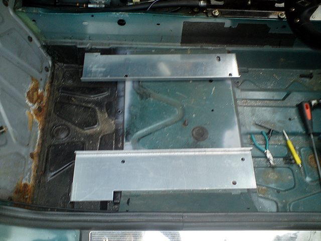 Picture 1A: seat mounting plates in situ in the car; they’re designed to meet up to the standard seat mounting points, and provide a flat, level mounting plate for what ever seats one wants to fit. I know of at least two other sets manufactured using these plans – and they seem to work well! |
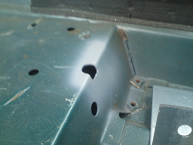 Picture 1B: the problem with a base mounted seat with the seat in the driving position I wanted – the cap bolts over lap the edge of the box section, which then needed to be cut out to accommodate them. A bit more work I’d rather have avoided if I am honest, but there you go! |
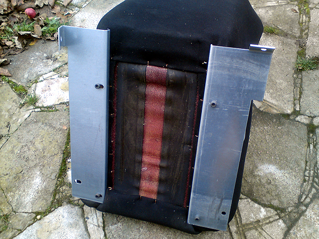 Picture 1C: mounting plates bolted to the seats (base mounted – used high tensile cap bolts as you may be able to see in this picture. |
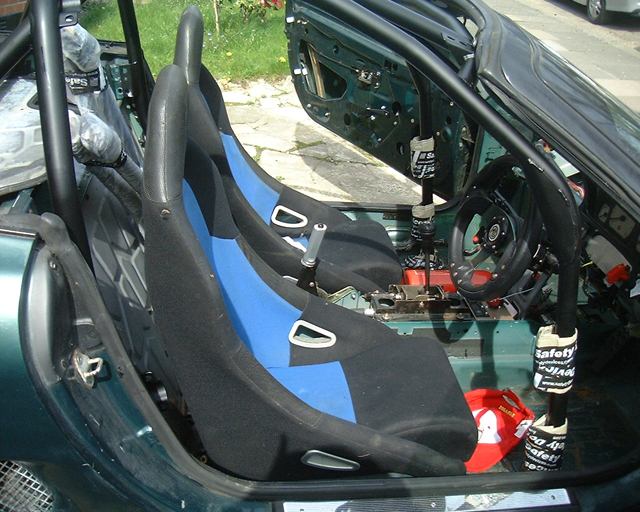 Picture 1D: a more recent picture showing the seats in situ. They’re quite upright – so I may have to look into tilting them back a little to improve comfort. You’ll also spot that the roll cage is resting in the car at this stage… |
So now I have rigidly mounted seats in Project Shed – another first. This now leaves the small issue of seat belts. The current plan is to use the standard inertia reel belts for road legality, and harnesses for track work. The inertia belt will mount using the seat mounts – which given that the belts bolt directly to standard chairs and the vehicle homologated with this arrangement, then what I am proposing should be fine. The tricky bit appears to be the buckle clasp. MGF standard ones contain explosive pre-tensioners. Project Shed doesn't have airbags, and I've removed the SRS ECU and wiring, and I don't fancy comedy exploding seats, so an alternative arrangement is being sought. More on this next time!
More MoT friendliness
With the idea of getting the Shed through an MoT has concentrated the thinking on switch gear. You need an illuminated switch for the rear fog lamps. Of course, I could fit an aftermarket switch, but there is nothing wrong with the standard switch, which is already compliant. But where to fit? Well, the FIA isolator switch is sitting there on its own bracket – and this seemed like a great place to mount the switch. I had to think a bit on how to do this – and in the end I cut up the standard auxiliary panel that usually resides below the heater controls. I cut a slot into the isolator switch panel, and could then side the switch mounts into this. I've transferred three into the panel: fog lamp, a heated rear window switch and a switch blank for the moment. Why a heated window switch? The Sprint season runs from Spring to Autumn – and I'll probably need some way of demisting the windscreen – and I am currently thinking of a detachable electric kit-car heater. I see that Moss now sells MGB windscreens with heated elements in them – here's hoping that they may do the same for MGFs (did anyone else see those flying pigs or was it just me?)
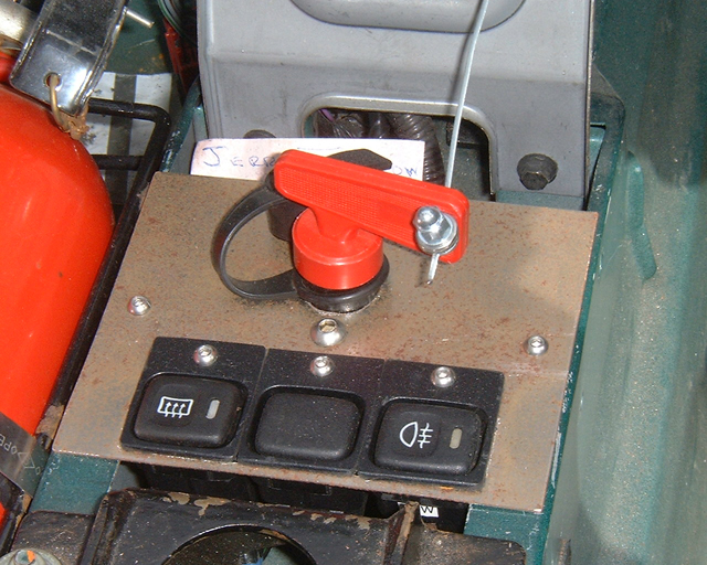 Picture 2A: ancillary switches (heated screen and rear fog lamps) mounted into the ignition cut off mounting panel – I’m quite pleased with the result. |
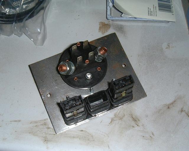 Picture 2B: rear of ancillary switch panel |
Talking of switch gear, I am also thinking about what to do with the door glass. Ultimately these items will be removed and either abandoned completely, or replaced with lexan. But that may be a "phase 2" project – so for the moment the windows – and window motors – stay. But where to mount the switches? Hmm. Do I really need two? Could I actually get away with just one switch that operates both windows together? If I can get away just the one switch, I may just mount it below the oil temperature gauge on the central dash support... I'll let you know next time how I decide to resolve this challenge.
Holy suspenders, batman!
Trying to coordinate with Tim, Project Shed co-conspirator, has proven increasingly difficult as our work schedules get progressively heavier – and Tim has just started his own business (which I am delighted to hear is going very well in its first year). However, we were able to get some joint "Shed time" the other weekend – and we decided that the next big thing to do was to check the suspension and fit the Bilstein shock absorbers, in all their yellow and blue glory. It bought these from Tech-speed motor sport about three years ago – so they were more than overdue to be fitted! I had, of course, removed the standard dampers ages ago – they come off easily enough, although a belt-type oil-filter removing tool is ideal to hold the body of the damper when undoing the top mounting bolt. Installing the new dampers proved reassuringly simple, although one of the lower mounting bolts (front nearside upper arm) had seized. At the rear, the suspension had been a victim of one of the earlier build deadlines – and so all the bolts here were checked for tightness against factory torque settings, the hub cleaned up with a wire brush and a splash of paint applied before reassembly. The upper ball joint was found to be in satisfactory condition on the nearside, so has been retained, and the rear anti-roll bar connected up. On the other side, things were not so simple. Bolt tightness were checked, but the thread on the upper ball joint was found to be in very poor condition – so replacement beckons. I have replacement ball joints, and a deep, 46mm impact socket purchased off the internet. But replacement usually involves removal of the old component, and that is the difficult bit at the moment. So far, despite having released the locking washer, the ball joint is stubbornly refusing to budge, despite using a 1.5 metre long breaker bar. I need an impact wrench – and my Chinese-made one bought cheaply from a "group buy" on Blatchat (a Lotus/Caterham 7 internet forum) is chocolate teapot useful. Grrr. As we speak, it is stewing in penetrating oil, in the forlorn hope that it will get easier to remove... I think I'll need to borrow Tim's compressor and air tools again.
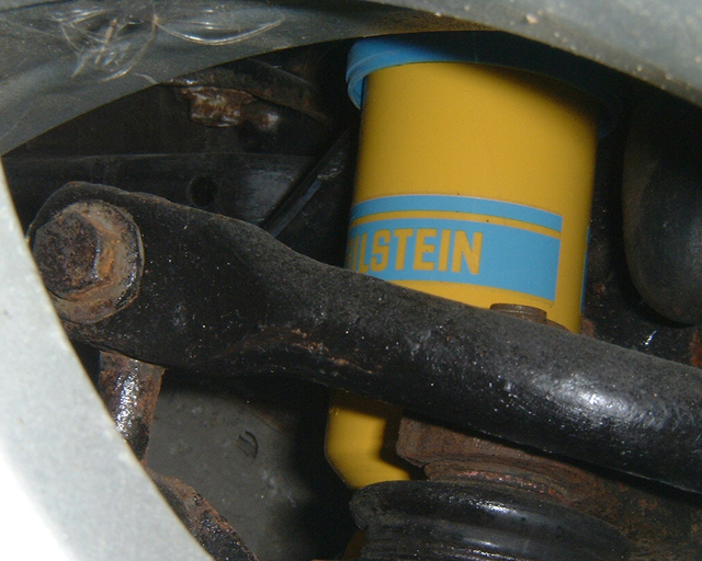 Picture 3A: Bilstein fixed-rate damper in position, looking fast without so much as going anywhere!
|
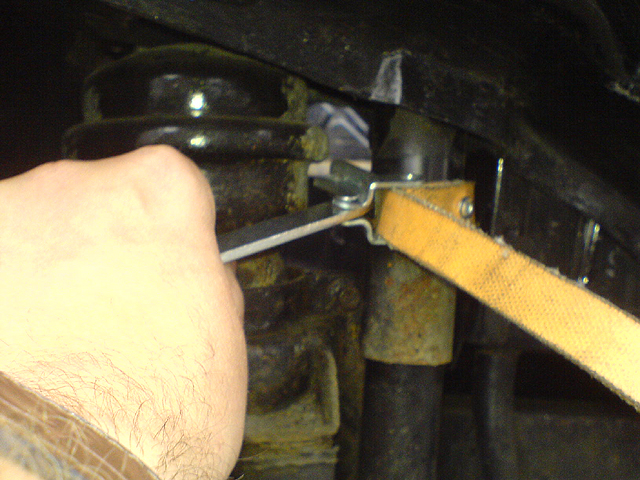 Picture 3B: the original dampers were readily unbolted, so long as the body of the damper is prevented from moving – something I achieved by using an oil-filter removal strap (leather type) – which securely holds the damper without damaging it. |
ABS sensor fun
The other problem on this hub is the ABS sensor. Shed watchers with incredibly good memories may recall my frustration a couple of years ago on the discovery that some rodent or other peckish mammal had chewed through a perfectly good ABS cable. I had another one ready to fit, so since we were here, unable to remove the ball joint, might as well tackle this little task.
As anyone who has ever attempted to remove an ABS sensor will tell you: don't. If you have a swear box, then I reckon you'll be able to afford a meal for two at the Fat Duck on its contents before you're even half way through.
Two problems here I think. One is the soft, 8mm-head bolt will readily round off before any useful movement is seen. If you apply heat, you melt the sensor. Best cut the bolt off. Thereafter the second problem appears: the bolt seizes/corrodes into the steel insert of the plastic sensor bracket. Getting this lot off after 15 years exposed to salt and road grime is likely to be a futile exercise – well it was here anyway. Brute force and heat was what eventually removed the old sensor and bracket. The "new" sensor would not come away from its mounting bracket, because (surprise surprise) the mounting bolt was seized in the metal insert. Great. But here at least, the insert was rotating in the plastic moulding. Good news. Bad news was that the sensor's bracket had lost its plastic locating lug, which prevents the sensor from rotating around its mounting bolt. As it happens, the old sensor bracket had left its locating lug in the hub! Common problems occur commonly I'm told. I over came the lack of sensor location by drilling a hole in the bracket , and screwing in a stainless self-tapping screw into the remnants of the old sensor's locating lug retained in the hub. Should do the job I hope!
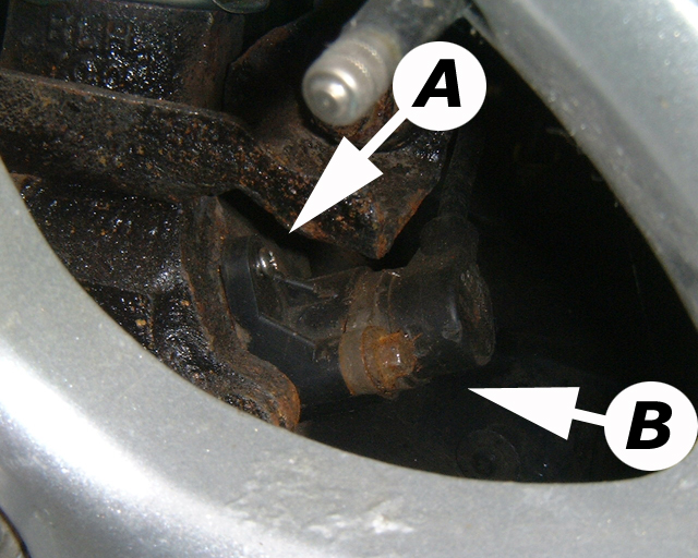
Picture 4: the ABS sensor: (A) – the stainless steel self tapping screw used to prevent the whole sensor from spinning around in its mounting – and (B) the ABS sensor itself.
Two steps forward...
So I shall leave this instalment with the Shed once again sitting on an axle stand, awaiting a new upper rear ball joint, and with another little Project Shed curve ball... a severely corroded nearside rear jacking point. Looks as though someone has been very clumsy with a jack as the nearside sill is heavily indented. Whether this has anything to do with the corrosion along the lower seam is another question, but this will need repairing before an MoT can be attempted. Nuts. I really do need to learn how to weld!
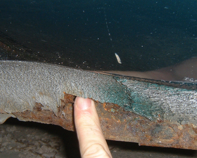 Picture 5: Holy Sill Batman! Those pesky steel worms have developed an appetite for the rear of the near side sill. I can get my figure in there! I need to learn how to weld now… |
 Picture 6: Charles and Olivia at the races – they told me that they won 9 world Gran Prix rounds and were the champions! Start ‘em young I say!!! |