The project build as
featured in
![]()
![]()
|
|
The project build as
featured in |
Part 14: Together in electric dreams
In the last instalment, I left you having stuck some daft stickers on the car and having bolted the front bumper back on the car, resplendent in mid-nineties specification orange front indicators. Kewl. But there remained quite a few unfinished jobs – principally, the electrical connections to the steering wheel and mounting the FIA ignition cut-off switch. Since many of the under-bonnet jobs had now been completed, time now to move rearward and to the inside of the car.
Wheel of fortune
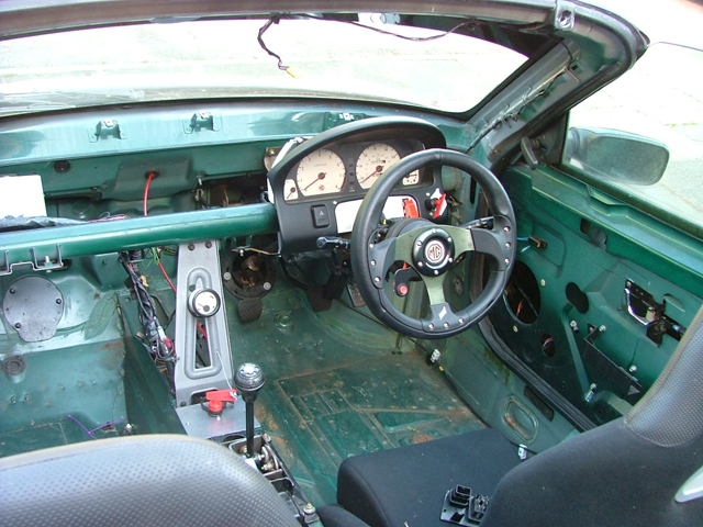
For dedicated Shed followers, you'll recall that I had been thwarted by the Momo designed steering wheel boss, required to fit the non-airbag equipped steering wheel that I'd bought off everyone's favourite internet auction site. The boss is a necessary adapter to enable the steering wheel to fit to the steering column, and is specific to the car that it is fitted to, so it is not uncommon to buy an aftermarket steering wheel without the correct fitting boss (although the major steering wheel manufacturers will usually be able to supply both). Certainly, the "MG" branded steering wheel that I had bought from a vendor in Hong Kong had no such adapter (despite being advertised as an MGF steering wheel), and I had to find a boss that would suit both the 'wheel and the MGF's steering column. As it turned out, my steering wheel used a mounting pattern identical to the now almost generic Momo item – and so the purchase of a Momo steering wheel boss rather lent itself as the automatic choice. This I bought from Demon Tweeks and it fitted perfectly on the steering column's splines, but there isn't enough space for the electrical connections on the rotary coupler. Before this project could be progressed any further, a solution needed to be found. Let us just say that I have given this a quite a lot of thought. Slept on it a bit. Chewed it over. Cobbled together a few ideas, disassembled the broken rotary coupler that I had from the donor car, and thought about it some more. This conundrum was starting to get really annoying. The solution I finally alighted upon is far from perfect, but it works.
I'd bought a perfectly functional rotary coupler off ebay some while ago, and now I was going to cut it up which felt wrong. But needs must, as they say. I carefully cut down the socket on the rotary coupler down to the base of the socket. Then I filed the inner edge with a 45 degree chamfer, and complete the bodge... er sorry... modification, I bend the copper terminals over 45 degrees. This meant that the plug in the steering wheel, which I had salvaged from one of the un-used steering wheels in my parts stash, could be attached to the rotary coupler at an angle. And, at last, the steering wheel could be pushed down on the column's splines, down onto its register, and the electrical connector cleared the steering boss. Hurrah! Multimeter time: start button worked; horn button worked. Hurrah! Job done. Steering wheel 19mm bolt nipped up, and the steering wheel assembled, and finally the steering wheel works are complete. And this means that the steering wheel remote starter circuit is also complete – well, almost, because now I need to complete it by installing the FIA-approved cut-off switch. But at least now I can grip a nice firm steering wheel, sitting in the car, making Mr Toad "Parp! Parp!" noises!
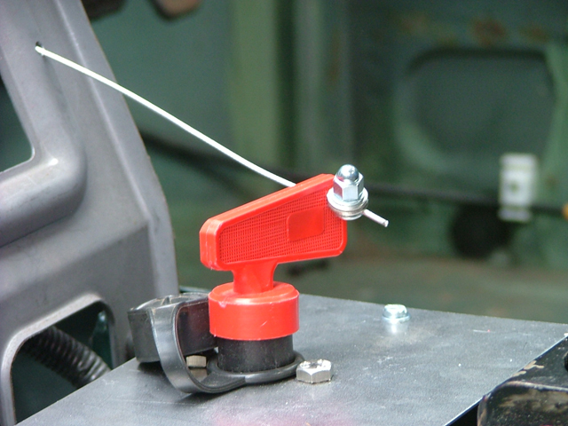
In event of emergency, twist and pull here
In the last instalment, I regaled you with how I fitted a remote T-handle to the scuttle panel, and routed the cable into the cabin. The next question was how and where to mount the FIA switch itself. Initially I had thought of fitting it over the top of the EPAS (Electric Power Steering) ECU on the nearside of the car, attaching a bracket between the dashboard support bar across the car and the bulkhead panel, but this wasn't really working for me: for one thing, there was insufficient space between the proposed mounting position and the EPAS ECU below it. Then I recalled that on inspection of the Vehicle Handling Solutions' MGTF sprint car of Andy Kitson, the kill-switch was mounted ahead of the gear lever. Hmm. That's a good place I thought: while it may be a bit of a stretch for a marshall to reach in and get at, they would have the external remote to play with, the central location of the switch itself would be in an ideal place for me, the driver, to pull if I needed to. Plus there was a gaping void there to make use of. Why not?
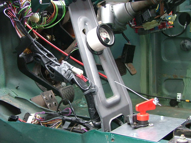
I got some 1.2mm mild steel plate off fleabay, cut it to size to suit the centre tunnel's width, and cut holes for the FIA switch. I also needed a means of fixing the plate to the car. The solution I employed were a pair of M4 rivnuts, purchased from a company appropriately called Make Ends Meet. Rivnuts are rather clever little fixings, a bit like a rivet, that can be inserted into a hole in almost any material. In it, they have a threaded section mounted on a compressible body. This compressible section expands like a middle-aged builder's midriff by tightening a screw, pulling the threaded section upward to the head of the rivnut, gripping the material into which they are inserted. Once inserted, they function like a captive nut – hence the name rivnut I guess: a rivet with a nut. So now I had a nice mounting plate for the FIA switch, ahead of the gearlever. Oh, except that the switch wouldn't fit into the space: not enough depth. In the last instalment, you may recall that I had mentioned that the FIA switch was pretty long? Well, this was proving to be the problem here; not for the last time is that switch’s length proving to be something of an inconvenience. The option I took was to cut a small square in the tunnel section below to provide the necessary depth the switch needed. Given that there was a much larger hole under the gear lever for the lever's counter weight to swing about in, I figured another, smaller hole, wouldn't make that much difference. This panel is clearly there for strengthening the centre spine of the car, and I was surprised at its thickness – probably around 2-3mm thick. I drilled a lot of holes, and then snipped around the perforations with a pair of tin snips, finally tidying with a file. A bit laborious, but given the constraints of space, the only option I had. Hole made, job done, the switch and its mounting panel fitted in snugly.
Now the remote pull-cable itself: I had replaced the MGF's standard pressed steel strengthening panel, which fits between the centre tunnel and the dashboard support tube, without giving too much thought about what I'd use it for, but it was going to become jolly useful. The pull cable needs a mount to hold the outer cable in a static position for the inner cable to transmit the movement of the handle – and that strengthening panel is in just the right place to retain the outer cable. By simply drilling a hole large enough for the inner cable to readily pass though, but small enough to prevent the outer cable falling through, the cable could be neatly routed to the FIA switch's key. Now I needed a small clamp at the end of the cable so when the remote handle is pulled, the cable will tug on the key, rotating and pulling it out of the switch. Halfords' cycling department provided something that was ideal – and the final result works a treat. All that remains now is to complete the wiring – and to do this, I'll need to re-route and modify the major power cables so that they fit to the newly fitted FIA switch. More on that story in a later episode!
More than just a cable holder
The transmission tunnel to dashboard support bar strengthening panel was to prove to be more useful than just a cable support; I was wondering where to mount the oil temperature gauge (and any other gauges that might prove useful in future). I had been thinking of gauge pods, but these are surprisingly expensive, and don't necessarily look all that robust, nor are they particularly aesthetically attractive. Pricey and rubbish looking – not a good combination. But there is that strengthening panel, sitting in the centre of the car... and I thought – why not mount the oil temperature gauge straight to that? Like earlier generations of Smiths and British Jaeger instruments familiar to all those with 1960's British cars, this clock had a pair of threaded bars on the back, which actually aren't used for anything on the standard car, but this pair of M3 threaded bars could be used to mount the clock to the strengthener – so a couple of holes later, and I was disproportionately pleased with the result – an oil temperature gauge neatly installed for nothing. Doesn't get better than that does it?
More wobbly than an frightened jelly fish on a tightrope
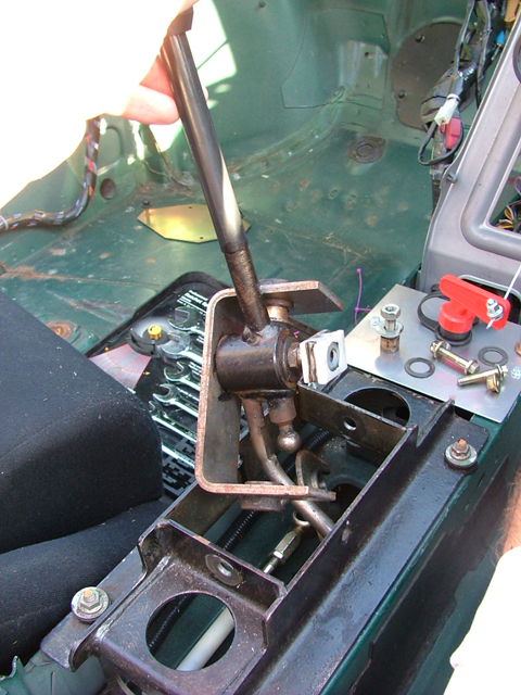
The MGF is endowed with a cable operated gear change – and for what it is, offers a remarkably good quality gear shift when in good condition. The gear lever that had come with the donor car had however done in excess of 100,000 miles and was loose and wobbly. Moving across the gate, the lever's counter weight would bang noisily against the sides of the centre tunnel – twang! Not good. This was a problem. There are a few quick-shift solutions on the market, variously offering reduced movement across the gate and improving the shift quality. All however cost money that I decided there wasn't budget for. As it happened, I stumbled across an on-line guide which suggested that you could erridicate the excess movement just by nipping up the three pivot bolts in the gearlever's gimble. Well, that's got to be worth a shot I thought. So I tightened them. Suspiciously, I didn't find them that loose in the first place, so I was neither surprised nor disappointed to find that the sloppiness of the gear lever was much as before. So I decided to investigate further, and disassemble the lever assembly and see where the wear was.
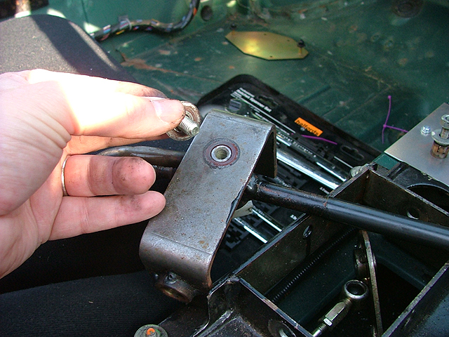
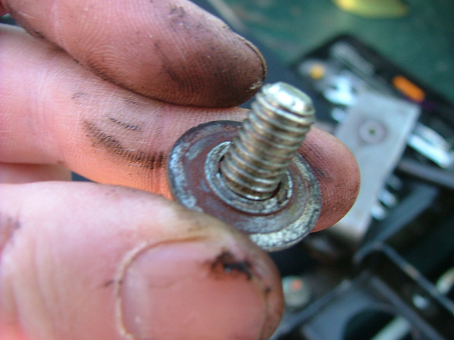
This is very easy if your car, like mine, has no interior trim to speak of (even the seats just lift out – no seat brackets fitted yet!). Undoing the gimble's pivot nuts meant that I could remove the gear lever while leaving the mount still bolted up in the car – and it was the removal of the fourth bolt, that retained the lever to the gimble that I found the problem: a heavily worn washer. It was worn and distorted, and as a result the bolt's shaft was free to move to and forth causing the sloppiness felt. I delved into a bag of stainless assorted nuts, bolts and washers, and replaced the worn washer with a new stainless item. Reassembling the lever to the gimble, I reconnected the gear change cable and tried out the gear change. Wow – what a transformation – the gear change felt like new again! I think that if I were to do this again, I'd grease up the inserts, which would take up what little play was left, but I was very pleased with what this little washer had achieved (read more here). So pleased, that I thought that I might as well modify the gearlever itself.
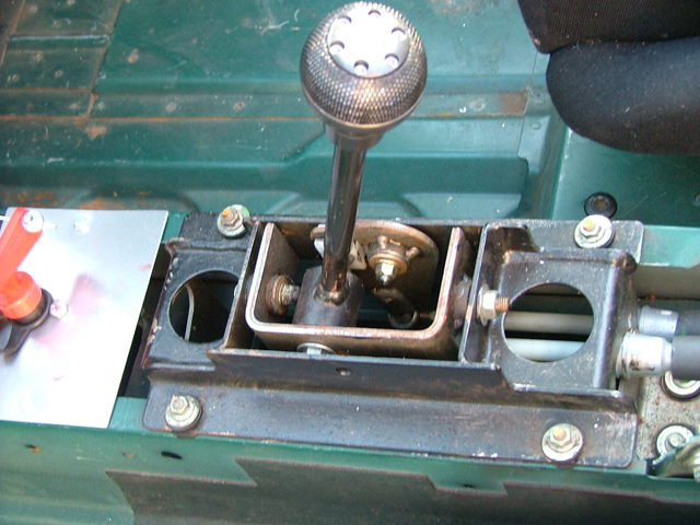
As I shall be sitting somewhat lower than standard, the standard gearlever length seemed somewhat excessive, so I decided to trim off about 15mm. I should probably have done this when I had the gearlever mechanism apart, but it wasn't too difficult to hack saw off the top 15mm of the gearlever by simply popping the lever into 1st gear, holding the lever with one hand and sawing with the other. Then I could pop the aftermarket gear-knob onto the lever, and tried the new combination for size.
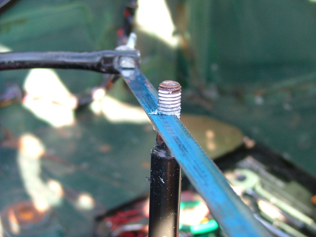
It feels pretty good. Whether I need to shorten the lever still further, I am not yet sure, but with an aftermarket gear-knob that uses grub-screw fittings, at least I don't need to be concerned about needing a thread for it to screw onto.
Sneak Peek
As I have moved into the centre of the car now, the other area that has needed finishing off are the seats. I want to use aftermarket Cobra "Clubman" seats. These ones are more supportive and lighter than the standard chairs – and because they're decidedly sheddy, were very very cheap too – 30 quid. From experience from a previous visit to Cobra Seats Ltd's manufacturing facility, I know that attempting to fit a seat to the standard MGF seat frames is not the best solution because you end up sitting even higher than you do in the standard seat – and since the standard seat is arguably too high in the first place – well, you get the picture.
How do they do it in the MGF Cup race cars? Easy – chop out the central strengthening spar across the centre of the car, and mount the seats off generic side mounted seat brackets on a 3mm 25mm square box section welded "H-frame" that goes across the width of the car between the sills. I confess that neither option – mounting the seats on standard runners or the full MGF Cup seat mounting option - were really floating my boat, and besides, my cheapo seats were base mounted.
So I've been thinking carefully at another solution – one that will pick up off the standard seat mounts, and mount the seats as close to the floor as is possible. The idea is to use 3mm mild steel plate (the preferred seat mounting material specs, although 5mm aluminium can also be used, according to the Motor Sport Association rule book), that will pick up off the standard seat mounting points. If these are strong enough to pass stringent motor vehicle homologation and NCAP crash testing, they should be adequate for Motor sport too. The seat will then be bolted to the plate, and the plate to the car – and job done. These mounting plates could be used again in future for side-mounted FIA-approved racing buckets, as the side mounting brackets could be fixed straight to them – so potentially a worthwhile investment.
This idea has gone through a few design iterations now, and I've looked for quotes from a number of steel/fabrication engineering companies – some of whom, it would seem, don't want the work given the daft quotes I've been given. Jeffark Engineering in High Wycombe however were very reasonable, and Dave Hollis, the company's owner, was very enthusiastic and helpful: he's building an AC Cobra replica, so he's clearly a fellow petrol head which almost certainly helped as he instantly understood what it was that I was after.
The final design drawings have now been sent off for manufacture – and I'll let you know how this works out next time!