![]()

|
MGF Headlamp disassembly |
There are a whole host of reasons why MGF headlamps may need to be taken apart. If your car is involved in an accident, for example, and the outer glass needs replacement, the glass cover can be purchased as a separate part (part numbers, below, right) to repair the existing damaged headlamp. This represents a useful saving over purchasing the whole new headlight.
Headlamp Glass Part numbers XBQ100710 for left hand XBQ100700 for right hand Each cost, from MG Rover, £46.59 + VAT (£54.74 each). |
Another reason why MGF enthusiasts may want to disassemble their head lights is to paint the outer reflector trim so that the headlamps mirror the style of the MGF Trophy 160 SE (see Andy Phillip's instructions).
A further reason may be to access the headlamp bowls for re-chroming when they've gone "misty" with age.
Therefore, knowing how to take your headlights apart can be most advantageous, and
hence the purpose for including these disassembly instructions here - I hope you find them
useful! ![]()
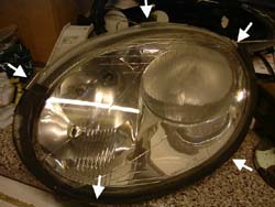
Location of outer glass retaining clips |
Time to dissemble headlights: 10-20 minutesPhilips head screwdrivers of varying sizes
A long, flat bladed screwdriver
An H6 Allen key
| 1. | Following Tim Woolcott's bumper and headlamp removal instructions, remove the bumper and headlamps as described. | ||
| 2. | Concentrating on the headlights now: remove the bulb-cover dust-caps (they unscrew a quarter turn, and pull off). Disconnect the electrical connectors to the main and dipped beam H7 bulbs. | ||
| 3. |
Five metal clips hold the headlight outer glass cover to the headlamp body. These are readily removed using your thumb under the clip's tab by pushing upward and outward (pictured opposite). Remove the outer glass cover; all that remains to hold it in place is a rubber seal. A little gentle persuasion with a flat bladed screwdriver may be required to prise the cover from the headlight assembly. |
||
| 4. |
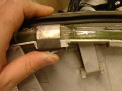
The headlamp assembly now comprises of two main components - the reflector assembly and the headlamp body (pale grey plastic). The reflector assembly is designed to be adjustable so that the light alignment can be adjusted (height and convergence of the beams). The reflector assembly pivots about a single ball joint (metal ball in a plastic cup) on the outer edge of the reflector assembly, where the adjustment is achieved by two threaded ball joints (plastic ball and cup) - the 'aligners' - at the centre of the upper and lower edges of the reflector assembly. The plastic aligner ball joints come apart readily with a little tugging to split them.
You can wind out the adjusters (H6 Allen key) to help you achieve this (pictured
opposite).
The pivot ball joint is a little harder. Use a flat bladed screwdriver to prise the plastic cup open a fraction (arrowed, right), whilst applying pressure to the reflector assembly to split the ball joint. This should come apart relatively easily and without damage if careful. |
||
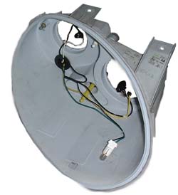
| 5. |
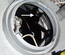
The reflector assembly is now free of the headlamp body. Withdraw the side light from the main beam reflector. This leaves the headlamp body, pictured opposite.
Pictured Left: inner reflector assembly, sans outer reflector (below, right), comprising of the main and dipped beam reflector bowls. Dipped beam deflector lens left in place. |
||
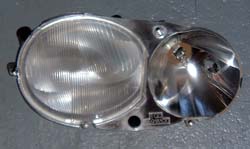
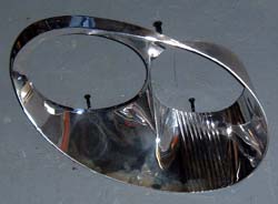
| 6. |
The reflector assembly can now to further dissembled. The outer silvered reflector is held onto the main reflector bowls by four small Philips head screws. Undo these, and prise off the outer reflector from the main reflector moulding.
Opposite: outer reflector removed from main reflector moulding. |
||
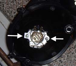
| 7. |
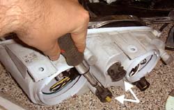
The bulb carriers can now be removed from the main reflector assembly. Both the main and dipped beam bulbs are held in place by two small Philips head screws (arrowed, opposite). Undo these, and withdraw the bulb holders. The headlamps are now completely dissembled. |
Reassembly of the headlamp is, in true 'Haynes Manual' tradition, a reverse of the disassembly instructions!
![]() But don't forget to re-align the
headlamps after they've been re-fitted to the car.
But don't forget to re-align the
headlamps after they've been re-fitted to the car.