
The 'Special K'
|
Words: Names Supplied |
|
|
The history of the K series Engine The 'Special K'
|
| Contents: |
Introduction |
The Beginning | Prototype to Production |
Damp Liner |
An engine to be proud of? |
The following article has been put together using published articles, reference material and anecdotes from former members of Powertrain - the engine development department at MG Rover Group, and its antecedents. This story is illustrated by exhibits on display at the Heritage Motor Museum at Gaydon.
Work began on a replacement for A series in the Advanced engines department of the Austin Drawing Office in
1984. Opinion was canvassed widely amongst automotive consultants and in particular the boffins at British Leyland Technology at
Gaydon where Spen King was in overall charge after the Jaguar-Rover-Triumph era. They had most famously developed the economy
prototype/concept vehicle called the ECV (read more on Keith's Austin-Rover
website, and see reference 1).
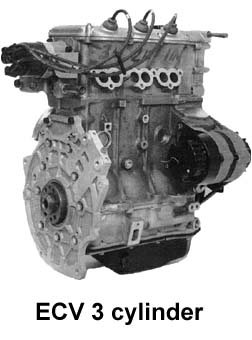 Interestingly, this car sported bodywork featuring bonded aluminium construction - revolutionary in its day and many years before
the appearance of the Jaguar XK220 and Lotus Elise. Of more direct interest to this
article, the ECV also featured a high-efficiency 3-cylinder engine (pictured
left), which was loosely derived from the E series. Despite what is reported elsewhere, this engine bears
no direct lineage to the K series - but this interesting engine did set the scene for later engine
development - of particular interest being the implementation of lean-burn
technology that British Leyland (BL)/ Austin-Rover had pioneered.
Interestingly, this car sported bodywork featuring bonded aluminium construction - revolutionary in its day and many years before
the appearance of the Jaguar XK220 and Lotus Elise. Of more direct interest to this
article, the ECV also featured a high-efficiency 3-cylinder engine (pictured
left), which was loosely derived from the E series. Despite what is reported elsewhere, this engine bears
no direct lineage to the K series - but this interesting engine did set the scene for later engine
development - of particular interest being the implementation of lean-burn
technology that British Leyland (BL)/ Austin-Rover had pioneered.
 The
aforementioned advanced engine research
team at Gaydon had developed the ports and combustion chambers
for all BL engines of this era (70s & 80s), including the
Jaguar AJ6, as well as the M, T & K series
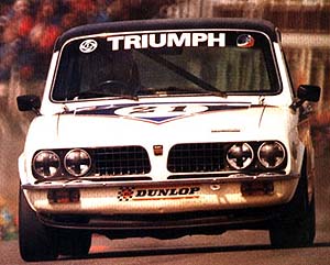
used in later Austin-Rover vehicles. The engines research team had been amongst the first to identify "barrel-swirl" or
"tumble" in 4
valve per cylinder engines (reference 2), and this
technology was first found applied in the
slant-four cylinder 16v engine installed
in the Triumph Dolomite Sprint of 1974 - a car that was very successful in the
British Touring Car Racing of the late 70s (pictured right) - the engine being extremely
efficient with high specific outputs. This engine preceded the current trend for
16 valve four cylinder engines by quite some years!
The
aforementioned advanced engine research
team at Gaydon had developed the ports and combustion chambers
for all BL engines of this era (70s & 80s), including the
Jaguar AJ6, as well as the M, T & K series
used in later Austin-Rover vehicles. The engines research team had been amongst the first to identify "barrel-swirl" or
"tumble" in 4
valve per cylinder engines (reference 2), and this
technology was first found applied in the
slant-four cylinder 16v engine installed
in the Triumph Dolomite Sprint of 1974 - a car that was very successful in the
British Touring Car Racing of the late 70s (pictured right) - the engine being extremely
efficient with high specific outputs. This engine preceded the current trend for
16 valve four cylinder engines by quite some years!
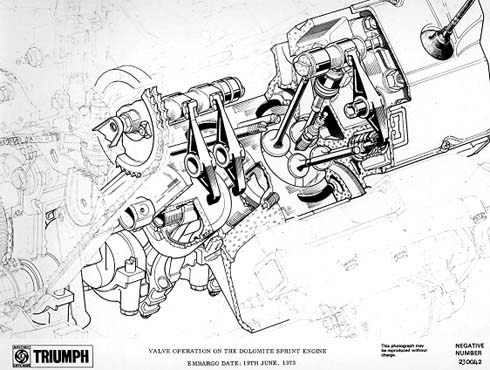
Interestingly, the ECV
3-cylinder, like the slant-four 16v installed in the Dolomite Sprint, used just
a single
over-head cam shaft to operate all 4-valves per cylinder - an ingenious cost-saving
arrangement (as shown below), but one that was not to be found on the later K series.
With the experience gained from the Triumph 16-valve engine and results from various research projects, Austin-Rover became leading advocates of lean burn combustion (high activity and dilution tolerance). Indeed, the K series was designed on the basis of this experience, and was intended to have stable combustion and low emissions out beyond an air/fuel ratio (AFR) of 20:1 (which is incredibly lean by then-current production engine standards - see reference 4). However, the environmental lobby scored a spectacular own-goal by insisting on such low levels of emissions of hydrocarbons and oxides of nitrogen that all manufacturers were forced to adopt catalyst after-treatment of exhaust gases (reference 3). On the K series, this development forced the use of a chemically correct (and much richer than originally intended) AFR of 14.5:1. This richer fuel mixture, combined with the added restriction that the catalyst in the exhaust system represented adversely affected efficiency the net impact upon fuel economy was a 5% increase in fuel consumption and thus CO2 emissions leapt up! (For more explanation on this, see the 'Lean Burn' box below.) Even so, the K series remained an extremely efficient and clean engine - it is not unheard of for uncatalysed K series engines to sneak through MoT emissions testing with a pass - albeit on a good day and a sympathetic MoT tester...
|
Lean Burn
The idea behind lean burn was to operate at part-load in such a manner that the thermal efficiency (the ratio of the useful work to energy in the fuel) would start to approach the diesel engine which always operates with excess air (or lean if you like) by dint of the fact it hasn't got a throttle. At full load a lean burn petrol engine may approach 33% efficiency, against the best diesels at 40% - the diesels get some advantage from the high compression ratio and smaller combustion chamber volume. It is on part-load that the diesel engines exhibit the biggest advantage in thermal efficiency. However the biggest single factor diesel has in its favour is that it is 13% denser than petrol, and we buy fuel by volume. The calorific value ( how much energy there is in a kg) is about the same. Thank heavens there's a limit to how many diesel cars there can be because when the crude oil is cracked, there is at least twice as much petrol as diesel - so someone has to burn the petrol. Its a sad fact that at best only a third of the energy in the fuel is used to propel the vehicle; about 20% goes to the coolant and is dissipated by the radiator and the majority of the rest goes down the exhaust pipe in the hot gases. There is another disadvantage to running too lean. At higher temperatures the nitrogen in the air breaks down or dissociates and starts to combine with oxygen to form NOx. This is nasty stuff causing asthma and all sorts of health complaints. It is probably NOx reduction that drove the legislators towards Catalysts rather than hydrocarbons. The emission levels from engines such as K were really low compared with older engines with Carburettors and dodgy ignition systems. As new rounds of the EU legislation came out, the amounts of CO and NOx permitted were reduced progressively so that Catalysts were the only solution. Ford and Peugeot, like Rover, invested a lot of time and resource into lean burn technology, but significantly, the German manufacturers didn't... |
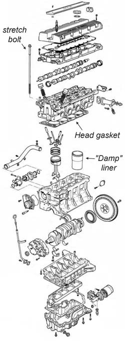
By 1985 the engine development team at Longbridge had designed, built and run the 3 (973 cc) and 4 cylinder (1300cc) concept design level engines. The specific output (bhp/litre) and light weight were astonishing straight out of the box. All the K series features were there in these engines: twin cams; 4 valves per cylinder; layered construction; long "stretch" bolts; wet liners; bedplate and low volume but high flow rate cross-flow cooling system etc. Even back then it was felt that environmental pressures would force downsizing of engines, so high output fuel efficient engines would be required in the future.
From Experimental Prototype to Production K-series
 By the end of 1985, the responsibility for subsequent design levels was handed over
to the Production Engine Team, who
up to this point had been working on 4 valve per cylinder versions of S and 0 series as well as the A+
engine for Metro. They set about
designing a mass-production feasible version of what was to become known as the K series.
They came up with an engine which is still a model in design for ease of
manufacture; the layered construction was one feature that enabled the use of Low Pressure Sand casting technique
for which Austin Rover own a number of patents. As part of the productionisation
of the engine, the crankshaft stroke was increased, raising the capacity to 1.4 litres
to capitalise upon an apparent tax break. In addition, a smaller capacity 1.1
litre engine was also developed, along with a more basic, and cheaper to produce 8-valve cylinder head
to give the new engine range an entry level. (For more on these developments, see
references 5 and 6.) This was also the time when the drawing boards all but disappeared
from the Austin Design Office (ADO) and CADCAM (Computer Aided Design/ Computer
Aided Modelling) was being adopted. CADCAM enabled
the wide use of mathematical modelling techniques which included Finite Element and
Computational Fluid Dynamics analysis, which was employed extensively on K
series to optimise the Noise/Vibration/Harshness (NVH) characteristics
(reference 7) and
thermo-mechanical performance (reference 8). In many ways, Rover were way ahead of the
competition in this regard (you only have to look at contemporary engines to see
exactly how far - an early 90s Ford Escort anyone? - Ed).
By the end of 1985, the responsibility for subsequent design levels was handed over
to the Production Engine Team, who
up to this point had been working on 4 valve per cylinder versions of S and 0 series as well as the A+
engine for Metro. They set about
designing a mass-production feasible version of what was to become known as the K series.
They came up with an engine which is still a model in design for ease of
manufacture; the layered construction was one feature that enabled the use of Low Pressure Sand casting technique
for which Austin Rover own a number of patents. As part of the productionisation
of the engine, the crankshaft stroke was increased, raising the capacity to 1.4 litres
to capitalise upon an apparent tax break. In addition, a smaller capacity 1.1
litre engine was also developed, along with a more basic, and cheaper to produce 8-valve cylinder head
to give the new engine range an entry level. (For more on these developments, see
references 5 and 6.) This was also the time when the drawing boards all but disappeared
from the Austin Design Office (ADO) and CADCAM (Computer Aided Design/ Computer
Aided Modelling) was being adopted. CADCAM enabled
the wide use of mathematical modelling techniques which included Finite Element and
Computational Fluid Dynamics analysis, which was employed extensively on K
series to optimise the Noise/Vibration/Harshness (NVH) characteristics
(reference 7) and
thermo-mechanical performance (reference 8). In many ways, Rover were way ahead of the
competition in this regard (you only have to look at contemporary engines to see
exactly how far - an early 90s Ford Escort anyone? - Ed).
K series went into production in 1988, funded largely by the Department of Trade and Industry (DTI). The production facilities were genuinely state of the art for the time. Both Ray Horrocks and Harold Musgrove had to put their jobs on the line (with huge credit to them) to ensure the investment that was to have such a positive impact upon the future of Rover.
The Engine Design Team now turned its attention to designing Vee engines based upon the K-series architecture. The team spent over a year designing a KV8 - but with no obvious vehicle platform that would make use of this power plant meant that no engine was ever built. Landrover had clearly been the intended recipient for this engine, but perhaps a V8 with double the capacity of a 1.8 four-cylinder - a mere 3.6 litres - was simply not adequate for the off-road division, who were by then using the massively torquey 2-valve per cylinder 4.6 litre Buick/Rover V8s in their top-range Range Rovers. What ever the reason for this engine not appearing, it is a great pity, as a KV8 would have been perfect for the RWD MG ZT! Fortunately, however, the KV8 development effort was not completely wasted, as eventually the KV6 for the Rover 800 and Rover 75 (and latterly, the MG ZS and MG ZT) came into fruition. Perhaps the most important development from KV6 that spilt over to the 4-cylinder variants was the introduction of the larger 80mm bore diameter - enabling the 4 cylinder K series to increase in capacity from 1.4 litres up to 1.8 litres. This bore increase was not without considerable technical difficulties, due to the thin-walled casting design of the original engine - effectively, it proved impossible to retain the top hung wet liner of the 1.4 litre. Cast in or sleeved liners (as found on the venerable Rover V8) would have involved considerable investment in boring and honing machines. The eventual cost-effective solution was the adoption of the pre-finished mid hung or 'damp liner' - a concept that was not too dissimilar in concept to contemporary Triumph motorcycle or Peugeot-Citroen engines. The resulting 1.6 and 1.8 litre engines quickly found applications within the Rover range: the 1.6 litre engine displaced the Honda engine in Rover 200 and 400 and the 1.8 litre was developed for the MGF and later filtered through to other Rover vehicles - ultimately including the Rover 75 in turbo-charged form. And then there was the VVC - which is another story! (Reference 10) The VVC to this day remains one of the most advanced cam timing systems available on a production car engine, uniquely being able to vary both phase and open-duration of the inlet valves. The result is an incredibly linear torque and power curve (compare with the stepped character of the Honda VTEC), with high specific outputs, yet retaining excellent emissions profiles.
K-series - an engine to be proud of?
References:
The IMechE website can be found @ www.imeche.org.uk |
The K-series was developed as a powerful and lightweight road-going engine capable of operating continuously at an engine speed of 6500 rpm (and intermittently higher than that - read more on the durability testing Rover employed in reference 9). The K-series is undoubtedly a durable engine; the bottom end is practically unburstable on engines that have not been tuned (and there is some latitude for tuning efforts within limitations, particularly with regard to engine speed). It is also worth looking in the back of Autocar and calculate some specific outputs of rival's comparable engines in the 1.4, 1.8 and 2.5 litre classes. The K-series manages 105 PS out of 1.4litres, 160 PS (VVC) & 200 PS (turbo) out of 1.8 litres, and 190 PS out of 2.5 litres - and don’t forget the four-cylinder engine weighs only 100kg (and the KV6 weighs in at an equally impressive 150kg)! Incredibly, after all this time, the K-series remains a class-leading engine. The fact that K series powered cars in its latest 2-litre guise is still winning races in the British Touring car championships 20 years after its inception speaks volumes. Over 3 million K-series engines have been built since the engine's introduction, and over 100,000 KV6s. The vast majority of these engines are apparently indestructible in practice (head gasket issues notwithstanding - Ed).
There are of course a significant number of un-named design and development engineers who put in valiant effort to make the engine the success it is - and just a few of these are mentioned in the references opposite. Nor should we forget the management who enabled it all to happen either. Following the troubled last decade of Austin Rover, Rover Group and finally MG Rover, the teams responsible for this remarkable engine have, sadly, been widely dispersed - to the extent that now the whole Automotive industry is littered with people who cut their teeth on K series - and a number of engines from former competitors now contain features pioneered on the incredible K-series. The K series is indeed one special engine - and its legacy will surely endure the sad demise of MG Rover Group in 2005.
The demise of MG Rover has lead to a number of "what if MGR survived?" scenarios that many enthusiasts have loved to speculate upon - myself included. Interestingly, the future of the K series was actively being researched and developed at the time of the group's collapse in April, 2005 - it appeared that despite the mounting financial problems, the management were confident enough of a positive outcome for negotiations with the Chinese Motor company, SAIC, to plough on forging the future of the K series. The most immediate hurdle for the K-series was the new European emissions regulations - widely referred to as EU4 (or EUIV) - that was due to be enforced by October 1st, 2005...
Work on the new EUIV compliant engines were, by all accounts, well advanced by the time of the company's collapse in April 2005 - with many engines already compliant (and only requiring some minor calibration to be completed) - including both the 1.8 litre K series engines employed in the MG TF, in both MPi and VVC guise. In the most part, all the K series required to get through the EUIV hurdle was some new engine management software and some additional electronic hardware - but the non-VVC 1.8 litre engines were to employ some interesting inlet system modifications. According to sources cited by austin-rover.co.uk, a "dual cam phasing system" was being developed - with operation similar in principle to BMW's Bi-Vanos system, with a mechanism not too far removed from that employed on the VVC. This new system was to be fitted to the MPi versions of 1.8 K series, increasing power from 120 to 140PS - a very useful improvement over the base engine, if not quite matching the impressive 160PS VVC. However, the new cam system would be somewhat simpler than the VVC, with obvious benefits in terms of cost, ease of production and reliability.
Interestingly, it was not just emissions and performance that the chaps at Powertrain were interested in - they were also developing a new head gasket system that could have gone a long way towards banishing the spectre of head gasket failure... Introducing the multilayer steel head gasket and up-rated oil rail!
Multilayered Steel (MLS) Gasket
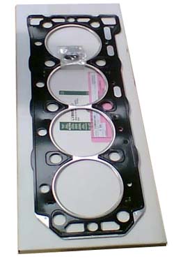 An interesting development was the new MLS gasket
- seen here, pictured to the right. The new gasket set consists of a steel
gasket consisting of 5 layers. In the centre is a
steel shim with swaged on fire rings - which appears to be very similar to the
original gasket designs. This, like the original gasket is encased
by two steel layers - rather like a sandwich. However, in contrast to the older
gasket design, rather than using
bonded-on 'elastomeric' butyl rings to contain the coolant jacket and oil drain
spaces, the gasket has an additional two steel layers on either side of the
gasket with swaged / raised areas to provide the coolant/oil void sealing (the
gloss-black layer just visible in the image opposite). These layers are there to help
prevent any coolant leakage failures - which, on the older gasket design, was
frequently due to peel-away of the butyl rings.
An interesting development was the new MLS gasket
- seen here, pictured to the right. The new gasket set consists of a steel
gasket consisting of 5 layers. In the centre is a
steel shim with swaged on fire rings - which appears to be very similar to the
original gasket designs. This, like the original gasket is encased
by two steel layers - rather like a sandwich. However, in contrast to the older
gasket design, rather than using
bonded-on 'elastomeric' butyl rings to contain the coolant jacket and oil drain
spaces, the gasket has an additional two steel layers on either side of the
gasket with swaged / raised areas to provide the coolant/oil void sealing (the
gloss-black layer just visible in the image opposite). These layers are there to help
prevent any coolant leakage failures - which, on the older gasket design, was
frequently due to peel-away of the butyl rings.
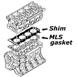 The
other interesting feature of the new gasket set is the so-called 'sixth layer'
or shim. The shim, as shown opposite (left), is
inserted
between the MLS gasket and the cylinder head, black surface uppermost. The shim is coated on both sides: on the upper side (the head-facing
side) with a dry sealant (it has the same black, glossy appearance to the gasket
face opposite) and the lower side is coated with an
inert
matt-grey treatment - and it is this side of the shim that comes into contact
with the upper surface of the MLS gasket.
The
other interesting feature of the new gasket set is the so-called 'sixth layer'
or shim. The shim, as shown opposite (left), is
inserted
between the MLS gasket and the cylinder head, black surface uppermost. The shim is coated on both sides: on the upper side (the head-facing
side) with a dry sealant (it has the same black, glossy appearance to the gasket
face opposite) and the lower side is coated with an
inert
matt-grey treatment - and it is this side of the shim that comes into contact
with the upper surface of the MLS gasket.
The shim appears to provide two main roles. Firstly it prevents the fire rings on the gasket digging into the cylinder head. When the head is torqued down, the fire rings are crushed between the liners and the cylinder head. The shim prevents the ring from digging into the head, and enables the 'ring to roll over the gasket layer in the manner in which it was designed.
Secondly, and the potential advantage of this system over the original gasket design, it acts as a protective layer to the cylinder head, a layer that comes into its own if the condition of the head is less than perfect. Examples of this is where the cylinder head has gone soft, or where the casting has an imperfection close to the combustion chamber; the shim will help prevent the liners hammering into the head in the fashion demonstrated here (although it has to be said that when the head becomes as damaged as the example shown, the shim will merely delay failure, not prevent it) or aid in sealing the fire walls.
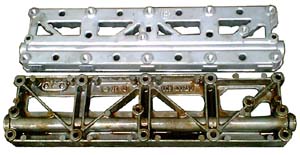 As part of the
MLS gasket kit, there was another intriguing development - a new lower oil rail
(this can be compared to the original oil ladder in the picture opposite, right
- the new oil rail is pictured top, the old, below - picture credit to Dr Dave
on mg-rover.org).
As part of the
MLS gasket kit, there was another intriguing development - a new lower oil rail
(this can be compared to the original oil ladder in the picture opposite, right
- the new oil rail is pictured top, the old, below - picture credit to Dr Dave
on mg-rover.org).
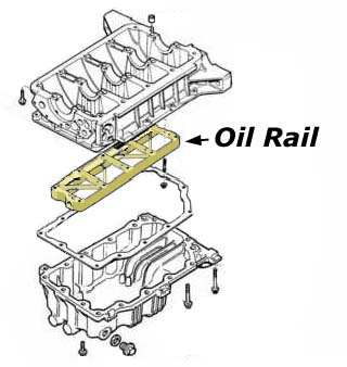 The oil ladder
is located underneath the crank bearing ladder at the base of the engine -
effectively representing the 'base plate' of the engine, and thus plays a
significant role in the stiffness of the assembled engine 'sandwich' as a whole.
The engine through-bolts (a.k.a. long or 'stretch' bolts) thread into the oil
ladder - which as can be seen on the figure opposite (left) can be viewed if the
engine's sump is removed.
The oil ladder
is located underneath the crank bearing ladder at the base of the engine -
effectively representing the 'base plate' of the engine, and thus plays a
significant role in the stiffness of the assembled engine 'sandwich' as a whole.
The engine through-bolts (a.k.a. long or 'stretch' bolts) thread into the oil
ladder - which as can be seen on the figure opposite (left) can be viewed if the
engine's sump is removed.
Made of 356 alloy rather than LM25 as in the original, the new oil ladder's alloy material has marginally better mechanical properties when compared to the original's LM25 - although, arguably, the practical difference between the two is minimal. Perhaps more significant, is way the way that two ladders are designed. In the image above, the two ladders are pictured in the same orientation - what you see is effectively the same surfaces as you'd see if you removed the engine's sump and viewed the ladder in situ from below. As can be seen, the new ladder (top) is boxed over, whereas the older ladder (bottom) has its strengthening webbing with its face abutting the base of the crank bearing ladder. Moreover, consider the width of the diagonal webbing - it is significantly thicker than that seen on the original oil ladder. Therefore, it would appear to suggest that the new ladder is designed to be far stiffer than the original design. That the new oil ladder also weighs 20% more than the original (figure provided by Roger Parker) lends further weight (excuse the pun) to the argument that the new ladder is indeed designed with torsional stiffness in mind.
According to the Land Rover service bulletin that covers the new MLS gasket,
the new oil rail MUST be fitted at the same time as the replacement gasket - so
it seems likely that the EU IV compliant K-series, had the engine made it to
this stage, would have come similarly configured. You'll notice mention of Land
Rover. This is significant as these two components are now available to buy - so
in the event of a head gasket failure on your K-series engined car, you can fit
these components as a direct replacement to the existing items in your engine.
Effectively, the EUIV hurdle would have been little problem for the Powertrain engineers; everything would have met the October 1st cut-off point for the change from EUIII to IV legislation. Some calibration work would have carried on after that date, but K series was ready to go and meet the challenge in 2005/2006.
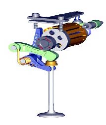 Perhaps
the most surprising development that was announced barely days after the MG
Rover Group entering administration (press releases dated on April 12th) was the
incredible camless valve actuation system, termed Intelligent Valve
Actuation (IVA) developed jointly by Powertrain and Camcon (read more
about Camcon Technology here). All production car engines
use cam shafts to open and close the inlet and exhaust valves but the limitation
of this is the fixed mechanical nature of a solid lump of metal: it forces a
compromise in terms of valve opening and duration that has to work over a wide range of engine speeds. Wouldn't it be
nice if the valve opening and closing could be optimised for ALL operating
speeds? To an extent, this is where variable cam systems have come in - but even
advanced systems such as MG Rover's own VVC has limitations. The optimum would
be to operate each valve independently - and this is where the IVA system really
scores. IVA posseses the potential to significantly
improve engine combustion efficiency, enhancing engine performance and fuel
economy, allowing each valve of the engine to be independently controlled.
Perhaps
the most surprising development that was announced barely days after the MG
Rover Group entering administration (press releases dated on April 12th) was the
incredible camless valve actuation system, termed Intelligent Valve
Actuation (IVA) developed jointly by Powertrain and Camcon (read more
about Camcon Technology here). All production car engines
use cam shafts to open and close the inlet and exhaust valves but the limitation
of this is the fixed mechanical nature of a solid lump of metal: it forces a
compromise in terms of valve opening and duration that has to work over a wide range of engine speeds. Wouldn't it be
nice if the valve opening and closing could be optimised for ALL operating
speeds? To an extent, this is where variable cam systems have come in - but even
advanced systems such as MG Rover's own VVC has limitations. The optimum would
be to operate each valve independently - and this is where the IVA system really
scores. IVA posseses the potential to significantly
improve engine combustion efficiency, enhancing engine performance and fuel
economy, allowing each valve of the engine to be independently controlled. 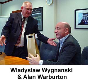 anism in operation).
IVA is what has been termed "Binary Actuating Technology," which uses a
"bi-stable" operating principle, utilising:
anism in operation).
IVA is what has been termed "Binary Actuating Technology," which uses a
"bi-stable" operating principle, utilising:This system, as demonstrated at the SAE conference, was shown to have a number of advantages:
Powertrain Ltd presented this camless engine technology at the Detroit 100th SAE Congress on the 12th April, 2005, the culmination of the 18-month joint research and development programme with Camcon Technology, the UK inventor and developer of binary actuation technology; the presentation of a technical paper demonstrated the progress that had been made to develop a camless engine prototype. Interestingly, since October 2004 Powertrain Ltd has had an exclusive licence agreement with Camcon to develop the technology in the automotive sector - although since the company entered administration, it is unclear as to the current status of this licence agreement.
|
A copy of the SAE Technical paper is available from
www.sae.org/congress/ Book Number SP - 1968, ISBN Number 0-7680-161-4. |
In press releases at the time, Alan Warburton (pictured sitting, above left, with Camcon's Wladyslaw Wygnanski), Powertrain Ltd’s then Engineering Director is quoted saying, “IVA technology enables us to have precise control over combustion by allowing each valve of the engine to be independently controlled. Key achievements include providing a number of stable valve lift positions and high energy efficiency whilst also supporting improved durability and noise levels. We believe that we have provided an innovative system to overcome the critical objections to electromagnetic valve operation; namely, 12V system compatibility, low power consumption and variable lift control. We can now offer to OEM’s significantly improved engine combustion efficiency with enhanced engine performance and fuel economy, whilst at the same time reducing engine emissions”.
It therefore appears that MG Rover got tantalisingly close to a real break-through engine technology that would have given the company a considerable march over many of its much larger competitors. With MG Rover and Powertrain now under the ownership of Nanjing Automotive Corporation of China, it is unclear whether this route of research and development will be pursued, or left on the scrap heap of "what might have been"...
|
About Camcon Technology Ltd. Based in Cambridge, UK, Camcon Technology is a small, fast-growing engineering technology company focused on the research and development of the Camcon binary actuator. Camcon binary actuating technology has been 15 years in development and is the invention of Camcon founder Wladyslaw Wygnanski (pictured with Alan Warburton above, left). The high-speed, low energy consumption, low heat dissipation and long life characteristics of the Camcon binary actuator mean that it has applications in a whole new range of areas, as well as being a replacement for existing actuator and valve technologies. Camcon Technology licenses its technology to customers, typically on a field-of-use basis. The company develops pre-production prototypes for customers on a consultancy basis and then hands over designs either to its customers to manufacture in volume, or to a manufacturing partner. For further information please visit: www.camcontec.com. Camcon is funded by ACUS Management Partners, an active management venture capitalist that specialises in funding early stage technology companies. For further information: www.acus.co.uk |
 When you burn any fuel that is a compound of Hydrogen and carbon the natural
by products are C02
and H20
(both inert). The amount of CO2
is emitted is directly proportionate to the amount of fuel burnt. In the
case of gasoline the chemically correct mixture of air and fuel is 14.5:1
- i.e. there is just enough oxygen to burn all the fuel. It's the fuel that
contains the energy. If we run richer than this stoichiometric ratio then
unburnt hydrocarbons must result (not enough oxygen to burn all the fuel)
and this mostly manifests itself as CO (carbon monoxide) and has to be dealt
with by the catalyst. When we start from cold on a rich mixture (not choke
these days but you know what I mean), it takes some time (circa 90 seconds)
for the catalyst to fully "light off" and deal with the unburnt
hydrocarbons. The problem is then that it has to be fed small amounts of CO
to stop it "going out" and it is this that precludes lean burn.
However it is a relatively small amount of fuel that is wasted. These days,
the after-treatment is so effective that in cities the exhaust gases coming
out are cleaner than the air going in (minus the oxygen of course).
When you burn any fuel that is a compound of Hydrogen and carbon the natural
by products are C02
and H20
(both inert). The amount of CO2
is emitted is directly proportionate to the amount of fuel burnt. In the
case of gasoline the chemically correct mixture of air and fuel is 14.5:1
- i.e. there is just enough oxygen to burn all the fuel. It's the fuel that
contains the energy. If we run richer than this stoichiometric ratio then
unburnt hydrocarbons must result (not enough oxygen to burn all the fuel)
and this mostly manifests itself as CO (carbon monoxide) and has to be dealt
with by the catalyst. When we start from cold on a rich mixture (not choke
these days but you know what I mean), it takes some time (circa 90 seconds)
for the catalyst to fully "light off" and deal with the unburnt
hydrocarbons. The problem is then that it has to be fed small amounts of CO
to stop it "going out" and it is this that precludes lean burn.
However it is a relatively small amount of fuel that is wasted. These days,
the after-treatment is so effective that in cities the exhaust gases coming
out are cleaner than the air going in (minus the oxygen of course).