![]()
EPAS Fault
Steering turning left? EPAS torque sensor reset
|
Words: Keith Starbuck |
|
|
Common Problems: Steering turning left? EPAS torque sensor reset
|
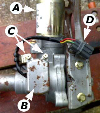
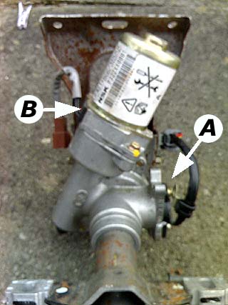 What you can't see: the steering column behind the dashboard is rather more than a simple shaft: it contains the steering torque sensor (A) and the electric assistance motor (B) - shown here in the correct orientation as though you had x-ray vision! |
An increasingly common complaint as the MGF gets older centres around its clever electrically assisted power steering system, EPAS. The complaint goes something along the lines of "The steering is much lighter to turn to the left than the right especially at low speeds..... it is not really as noticeable at higher speeds" or more simply, "help, my car's steering is turning left by itself!"
If your car is suffering from this problem, and you were to raise the front of the car on axle stands and turn on the ignition, you'd probably find that the steering self-steers - the most common direction being to the left.
The problem can be either be electrical, or due to wear in the steering column mounted torque sensor assembly.
An electrical problem?
Tackling the easiest option first: dirty electrical contacts. Thus the first task is to spray contact cleaner onto all the EPAS ECU connectors - this will solve a good number of curious EPAS related faults. The EPAS ECU is mounted above the glove box on the passenger side of the car - you can see more on how to access this here (Will Munn's EPAS bypass switch option). However, if this fails, then the chances are you've got a problem with the steering column's torque sensor.
A problem with the EPAS torque sensor?
Unfortunately, the EPAS torque sensor is regarded my MG Rover as a non-serviceable replacement item - so any garage that you take your car to is very likely to simply replace with new - landing you with a bill of in excess of 500 quid for a brand new steering column. Ouch.
However, it is possible for a skilled DIY enthusiasts to re-set the torque sensor
which is exactly what Keith Starbuck has done.
Introducing the Torque Sensor
|
0V █ █ █ █ █
█ █
█ █ █ █ █
+5V Figure shows a
cartoon of how the torque sensor in the EPAS steering column works.
Essentially, the torque sensor consists of two potentiometers; the output
signal is the difference between the two. Steering straight-ahead, and the
signal is 0. turn the wheel in one direction or the other, and you'll find
either a positive or negative voltage output - as explained further in the
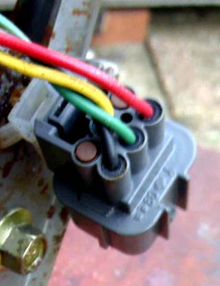
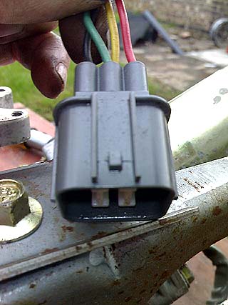
text below. Picture (left) shows the back of the EPAS loom plug - demonstrating the colours indicated in the text. The red wire carries +5 volts, black is ground, and the green and yellow wires carry the 'sensor outputs' A & B indicated above. |
The MGF power steering is different in design to most cars, assistance being by a sensor and electric motor mounted on the steering column; the actual steering rack itself is not power assisted. When the driver turns the steering wheel the force needed is mechanically transmitted to a sensor on the steering column. This sensor converts the movement and thus the force needed to turn the wheel, into an electrical voltage. This voltage is then fed to an ECU which drives the motor to provide the assistance required.
The sensor is effectively a dual linear 2K potentiometer wired up as shown in the top figure, right.
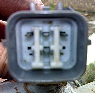
Sensor wires are coloured (the back of the loom plug is shown below right):
+5v: RED
0v (ground): BLACK
Sensor outputs A & B: YELLOW and GREEN.
When there is no turning force on the steering wheel, the sensor should be adjusted such that the voltage at sensor output A and B are equal. Thus, at rest, the wiper of each of the potentiometers (indicated by "▲" in the middle diagram, right) sit at 2.5 volts (half of the supply).
As you pull on the steering wheel and twist the torque shaft, the wipers of the potentiometers both move to either the left or right (of the diagram), so one wiper increases in voltage and the other decreases). This is the signal that is fed to the ECU to tell it to drive the motor to assist you in whatever direction you are turning the steering wheel.
Wear and the Torque Sensor
So that there is no play in the sensor, the potentiometer lever arm is spring loaded and runs on one side of the slot in the torque shaft. Any wear on the torque shaft, potentiometer arm, or movement of the sensor adjustment causes the sensor to go slightly out of position at rest. As mentioned above, the two sensor output voltages should each sit at 2.5V when the steering is at rest and straight ahead. Thus the difference between the voltage at the 2 wipers should be zero and the ECU doesn't fire up the motor. If this is not the case, and one of the sensor voltages is higher than the other, the steering assistance motor assumes that you are attempting to steer and will apply an assisting steering torque - leading to that well-known 'self-steering' phenomenon. If you are attempting to resolve a steering problem, you need to try and restore the equilibrium between the two steering sensor outputs.
Re-setting the Torque Sensor
Tools required
|
Materials required
|
Time required
|
How to establish if the sensor needs resetting
Before doing anything you need to establish if
the actually sensor needs resetting. The easiest way to do this is to raise both front
wheels off the ground, ensuring that the car is stably supported on axles stands and
switch on the ignition. Turn the wheels to straight ahead and let go of the
steering wheel. If the cars front wheels steer by themselves (usually to the
left) the sensor needs resetting. If the wheels do not steer themselves (making
sure that the EPAS fault light has gone out), the sensor is correctly
positioned, and you need to look elsewhere for the cause of your car's steering
problem.
How to reset the sensor
Basically there are 2 ways to accomplish this:
Procedure for resetting the sensor with a digital voltmeter.
| 1. | Disconnect the car battery
and raise the front wheels. Ensure that the car is stable and mounted
securely on axle stands. |
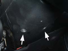
| 2. | Remove the fuse cover paned flap by turning the 2 plastic screws 90 degrees and loosening the 2 screws holding the hinge part to the bottom of the dash. |
| 3. |
 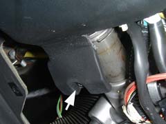 The next step is to remove the lower steering column shroud. Although not necessary, it should provide a little more working room. |
| 4. |
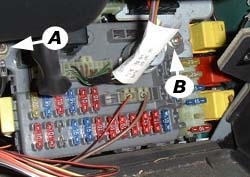 To gain access to the sensor, loosen the fuse panel and move it slightly to the
right. There are two retaining bolts - the left most is shown arrowed, A, the
other is on the other side adjacent to the yellow relay, arrowed and
labelled B. To gain access to the sensor, loosen the fuse panel and move it slightly to the
right. There are two retaining bolts - the left most is shown arrowed, A, the
other is on the other side adjacent to the yellow relay, arrowed and
labelled B. |
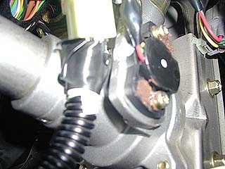
| 5. |
 Using the
T25 torx security bit (some sensors however, as shown in this picture, use ordinary bolts) remove the 2 bolts
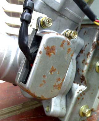
securing the metal cover over the sensor. Using the
T25 torx security bit (some sensors however, as shown in this picture, use ordinary bolts) remove the 2 bolts
securing the metal cover over the sensor.Obviously this is a lot easier if the steering column has been removed from the car - as is the case for the example shown in this picture! |
| 6. |
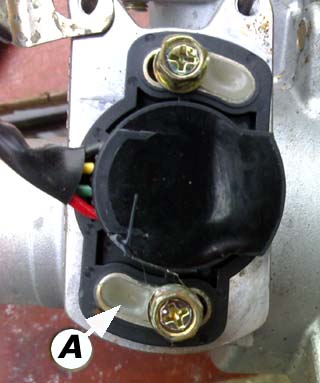 Using a craft knife, pick out the glue
(labelled here as 'A') from the 2 adjusting slots securing the
sensor. There is no need to pick it all out as the sensor will only need to be
moved slightly from its current position. Using a craft knife, pick out the glue
(labelled here as 'A') from the 2 adjusting slots securing the
sensor. There is no need to pick it all out as the sensor will only need to be
moved slightly from its current position. |
| 7. |
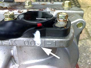 Mark the sensor position with paint
or tippex (as arrowed) so that you can easily move the torque sensor back to this
original
position. Mark the sensor position with paint
or tippex (as arrowed) so that you can easily move the torque sensor back to this
original
position.
Loosen (only slightly) the 2 sensor mounting bolts. The sensor will spring to a new position as soon as the bolts are loosened. |
| 8. |
 Unplug the sensor at the steering column connector. Unplug the sensor at the steering column connector.
Extend the wires from the connector (going to the sensor) by plugging the 4 wires onto the spade terminals of the connector.
Remember, the sensor wires are coloured as follows:
Set the meter to DC volts (say 10 volt range). |
| 9. | Connect your 6 volt battery between the 0v and 5V wires (BLACK and RED, polarity is not important) and the digital volt meter between sensor A and B (GREEN AND YELLOW, polarity of meter is not important). The meter will read a small voltage (either positive or negative). You will have to crank the meter range down to millivolts. |
| 10. | Turn the sensor by hand. You will see the meter reading drop to zero (as you
near the original position, indicated by your paint mark) and then , as you
continue turning the sensor, read voltage of the opposite polarity.
DO NOT PUT ANY FORCE ON THE STEERING WHEEL BY LEANING ON IT OR YOU WILL AFFECT THE READING. When you have found the position of the sensor when the meter reads as close to zero as possible (ideally below 10 millivolts (ignore the polarity). Retighten the sensor bolts (you might have to repeat the process as the sensor tends to slip a little during tightening). |
| 11. | Remove your wires and reconnect the sensor plug.
Temporarily refit the fuse panel and make sure that you haven’t left anything which could short out any connections (the odd screwdriver or spanner). Reconnect the battery and start the engine. Repeat the "How to establish if the sensor needs resetting" procedure. |
| 12. |
 Job
Done! Job
Done!When you're happy that the sensor is in the correct position, you can apply some more hot glue (or silicone sealant, as Darren has done here) to ensure that sensor is now retained properly in position). |
Procedure for resetting the sensor without a digital voltmeter, trial and
error.
| 1. | Disconnect the car battery
and raise the front wheels. Ensure that the car is stable and mounted
securely on axle stands. |
| 2. | Remove the fuse cover paned flap by turning the 2 plastic screws 90 degrees and loosening the 2 screws holding the hinge part to the bottom of the dash. |
| 3. |
The next step is to remove the lower steering column shroud. Although not necessary, it should provide a little more working room. |
| 4. |
To gain access to the sensor, loosen the fuse panel and move it slightly to the
right. There are two retaining bolts - the left most is shown arrowed, A, the
other is on the other side adjacent to the yellow relay. |
| 5. |
Using the
T25 torx security bit (some sensors however, as shown in this picture, have ordinary bolts) remove the 2 bolts
securing the metal cover over the sensor. Obviously this is a lot easier if the steering column has been removed from the car - as is the case for the example shown in this picture! |
| 6. |
Using the craft knife pick out the glue
(labelled here as 'A') from the 2 adjusting slots securing the
sensor. There is no need to pick it all out as the sensor will only need to be
moved slightly from its current position. |
| 7. |
Mark the sensor position with paint
or tippex (as arrowed) so that you can easily move the torque sensor back to this
original
position.
Loosen (only slightly) the 2 sensor mounting bolts. The sensor will spring to a new position as soon as the bolts are loosened. |
| 8. | Turn the sensor until the paint line on the sensor part is just below its original position. |
| 9. | Temporarly refit the fuse panel and make sure that you haven’t left anything which could short out any connections (the odd screwdriver or spanner). Remove your metal watch etc. |
| 10. | Reconnect the
battery and start the engine. Repeat the "How to establish if the sensor needs resetting" procedure. You might find that the wheels turn in the opposite direction, in which case you have gone too far with the sensor position. Repeat the above with the sensor in various positions ( but always near to the original paint mark) until you find the best position . |
| 11. |
After
you've finished, make sure that both sensor adjusting bolts are tightened
(but don’t over tighten them!).
Fill the 2 slots with hot melt glue and replace the metal sensor cover. Make sure that the fuse panel has been refitted correctly and refit the cover flap. |
| 12. | Road test! |
|
Hot Tips to remember:-
Location of major EPAS components on the steering column:
A: Mounted near vertically, the assistance motor |
If you are methodical in your approach, then resetting the torque sensor is not an especially difficult task - and has been one that has been successfully attempted by a number of MG enthusiasts now. The final words are appropriately Keith's: "I hope this is of some use; it's been 2 years since I reset mine and I've had no further problems."