|
Words and Pictures: Will Munns, |
|
This page contains: Introduction | EPAS over-ride circuit | The relay | Parts required | Over view | Fitting instructions | Verdict |
|
|
EPAS Over-ride switch
|
The MGF combined a number of novel design firsts when introduced to the motoring public in 1995. It was, for example the first small, affordable, mid-engined convertible sports car (the Fiat X1/9 being a targa rather than a full convertible). With this layout brought certain design challenges - not least as to how to provide power assistance to the steering (a marketing necessity these days) where the traditional source of hydraulic assistance, the engine, is placed so far away from the steering column and steering rack. The solution was Electric Power Assisted Steering (EPAS) - a solution only previously found on the relatively exotic Honda NSX. Thus, the first 'mass' produced car with EPAS was born.
Whilst EPAS was a brilliant solution to a whole host of design problems, and proffers a number of very real advantages over hydraulic assistance (reduced energy consumption being one), early releases of EPAS attracted criticism from motoring writers and enthusiastic drivers alike. The problem was whilst the system reduced assistance with increasing speed, its interference at low speed robbed the driver of a significant degree of steering feedback. For this reason, a significant number of 1.8is were specified pointedly without EPAS, and MGFs that venture onto the track usually have the system switched off.
|
|
Switching off the EPAS on a car so equipped does have a surprising effect on steering feel - in low to medium speed corners, the steering has more weight and markedly more feel. Even at motorway speed, there is an appreciable difference in steering feel, even though, at these speeds, the EPAS assistance should have been reduced to practically nil. However, disabling the EPAS by removing its main power fuse (located under the bonnet) is hardly convenient when you come to park the car. Some may recall the TV adverts for the Fiat Punto (2000/2001) - the one where boy chastises the presence of what he referred to as a 'girlie' button: a button that could switch the power assistance on or off. Thus seeded the idea for the EPAS cut out switch discussed here.
The original idea was to insert a 40amp relay in line with the EPAS main
power relay, but during these discussions, Will Munns
came up with a far more elegant solution which is detailed here.
The EPAS Over-ride Switch Circuit
The EPAS Over-ride Switch The air conditioning air re-circulation switch (pre-2000 model MGF, part # YUG101720, post 2000 MGFs and MG TFs, part # YUG102600PMP) is a toggle switch, so it stays in whichever position it was left in. With the circuit design shown here, you can chose to wire the relay to positions 3 or 4 on the switch, to chose whether to have the switch warning light-on, PAS-on or switch warning light-on, PAS-off combination.
The other advantage of this particular switch is that it comes with a neat, circular arrow logo that seems to fit the concept of Power steering quite nicely. Unfortunately the switch will only fit into the passenger side blank because Rover have keyed the switches and their apertures. However, you could remove the keying with a small file so the switch is closer to hand for the driver (which is exactly what I've done for my car). The EPAS Over-ride Relay The fuse protecting the EPAS ECU is rated at 10 amps (fuse #1 in the cabin-mounted fuse board), but the ignition-switched cable is only used (according the wiring diagram) to switch on the EPAS, so the current demands are unlikely to be anywhere near this level. If you are feeling really excessive then a 10A relay would be the one to choose. Maplin do a good selection of relays for under £5 (keep going through the catalogue until you find one that is in stock). You can probably get away with a 1 or 2 Amp relay, but I would play safe and buy a 5 Amp version (the relay we'd recommend is part# QC58N - and is the relay that is discussed in the installation instructions below). The relay is mounted locally to the EPAS ECU; there are a few screw holes that are suitable for cable ties in the vicinity. This also it means that there are only two long wires to the switch. The other wires for the switch are sourced locally (red/black and black can be sourced from any of the other switches). |
||||||||||
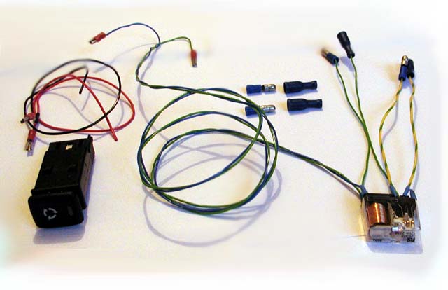
Parts Required: Assembled together the kit of parts will look like those shown opposite, right.
Relay (#2): recommended QC58N @ £4.99 from Maplin. Bullet connectors - male and female Wire (5amp) - probably sensible to have a range of colours so you don't get confused Either a set of small 5A female spade connectors, or a second hand connector block to suit the switch being used. |
|
|||||||||
| Fitting
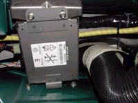
Overview: Remove the glove compartment, from the foot well looking directly upwards you should see the EPAS ECU (electronic control unit) - as picutured opposite. |
|
|||||||||
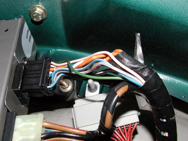
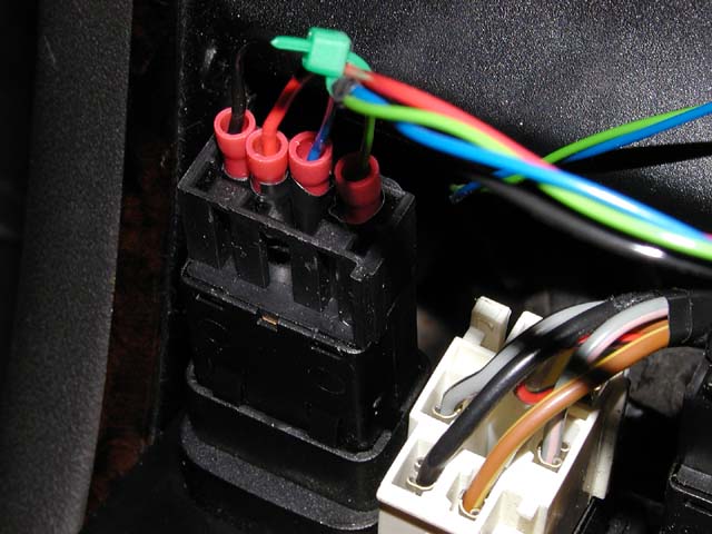
A closer look at the wiring loom Points to note:
|
|
|||||||||
View from behind the switches Points to note:
|
|
|||||||||
Fitting instructions
![]() Before
commencing work, disconnect the battery - but please ensure that you have all
radio codes safely recorded before doing so.
Before
commencing work, disconnect the battery - but please ensure that you have all
radio codes safely recorded before doing so.
| 1. |
 Step one is to remove the
glove box (described in more detail
here) so as to be able to visualise the EPAS ECU mounted under the
dashboard. Step one is to remove the
glove box (described in more detail
here) so as to be able to visualise the EPAS ECU mounted under the
dashboard. |
||||||||
| 2. |
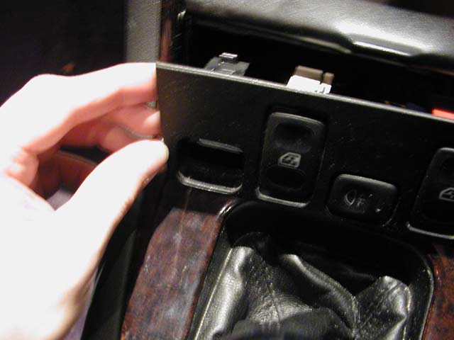 The
next step is to pop out the switch panel so as to gain access to the rear of
the switches and the wiring loom. On Mk1 MGFs, this is quite easy to do -
the switch panel pops out if pushed out from behind (remove one of the
quarter panels in the foot well containing the courtesy light to get you
hand behind the panel) or use a flat broad bladed instrument. For Mk2/
MY2000 MGFs and MG TFs, this job is somewhat harder in that the switch panel
is part of the centre console, so you are forced to work from behind the
dash (or remove the centre console in its entirety, which is probably the
route that I'd take). The
next step is to pop out the switch panel so as to gain access to the rear of
the switches and the wiring loom. On Mk1 MGFs, this is quite easy to do -
the switch panel pops out if pushed out from behind (remove one of the
quarter panels in the foot well containing the courtesy light to get you
hand behind the panel) or use a flat broad bladed instrument. For Mk2/
MY2000 MGFs and MG TFs, this job is somewhat harder in that the switch panel
is part of the centre console, so you are forced to work from behind the
dash (or remove the centre console in its entirety, which is probably the
route that I'd take). |
||||||||
| 3. |
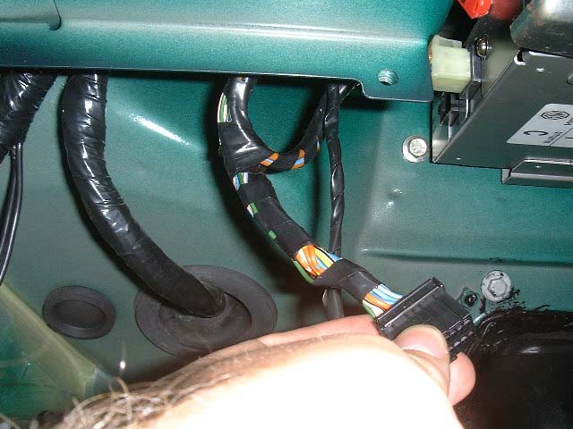 Returning
to the EPAS ECU, we're coming to the brave bit: identifying and cutting the
green EPAS ECU power cable and the pink/blue EPAS warning lamp wire. The
first job is to disconnect the loom plug from the ECU. Returning
to the EPAS ECU, we're coming to the brave bit: identifying and cutting the
green EPAS ECU power cable and the pink/blue EPAS warning lamp wire. The
first job is to disconnect the loom plug from the ECU.The plug in question, as can be seen in the picture to the right, is to the left of the ECU. It's all very neatly taped up, so we'll have to remove some of the binding to access the cables that we need. |
||||||||
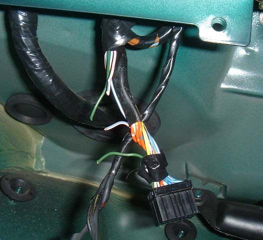
| 4. |
 Now
identify the green power cable and the pink wire with the blue tracer - they
are the cables pictured right. Now
identify the green power cable and the pink wire with the blue tracer - they
are the cables pictured right. |
||||||||
| 5. |
 Brave
pill time: these wires have to be severed. The point of no return! Brave
pill time: these wires have to be severed. The point of no return!Now strip the tips of these cables, and attach the male and female bullet connectors such that if you want to reverse this modification at some point in the future, the relay can simply be unplugged, and the wires reconnected together. For convention, put the male connectors on the wires from the ECU connector, and the female connectors on the wires to the instrument binnacle/ EPAS motor. |
||||||||
| 6. |
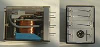 Now have a
look at the relay you've bought. Pictured right is the two views of the
relay that Will recommends - QC58N, which is available from Maplins. The pins are numbered as
shown below: Now have a
look at the relay you've bought. Pictured right is the two views of the
relay that Will recommends - QC58N, which is available from Maplins. The pins are numbered as
shown below:
The task now is to solder wires onto the relay itself. Pin 1 will go to B' - the pink/blue wire to the EPAS ECU. Pin 4 goes to A' - the green wire that derives from fuse #1. Pin 9 goes to B - the pink/blue wire that goes to the steering column, and pin 12 goes to A - the green wire to the EPAS ECU. Pins 13 and 14 will go to the dashboard-mounted switch. For pins 1, 4, 9 and 12, solder on four short lengths of 5amp wire - 10cm lengths should be more than sufficient to allow you to mount the relay close by. Put male connectors onto wires leading from pins 4 and 9, and female to wires connected to pins 1 and 12. For pins 13 and 14, we need to solder on a long length of wire (about a metre - best be generous at this stage, and trim down to a more suitable length later) so that we can control the relay from the dash mounted switch. We'll also need a power supply for this switching operation, so solder on a linker wire between pins 4 and 14 - so that the EPAS bypass switch is powered by the same fused power supply as the ECU (green wire from fuse #1). |
||||||||
| 7. | Now connect up the relay into the EPAS wiring loom, and mount the relay securely with cable ties near the EPAS ECU. Run the long cables from pins 13 and 14 down the rear of the centre console to the switch panel. | ||||||||
| 8. |
 The
next step is to wire up the dash-mounted switch (YUG101720 for the Mk1 MGF
shown). There are two options here - option 1 is to use small spade
connectors (readily available from sources such as Halfords). Attach the
spade connectors and connect the wire from pin 13 on the relay to pin 4 on
the switch. The wire from pin 14 on the relay connects to pin 5 on the
switch. Pin 1 goes to the instrument common earth, while pin 2 is the
instrument illumination, so take a spliced feed from the red/black
instrument illumination cable. The
next step is to wire up the dash-mounted switch (YUG101720 for the Mk1 MGF
shown). There are two options here - option 1 is to use small spade
connectors (readily available from sources such as Halfords). Attach the
spade connectors and connect the wire from pin 13 on the relay to pin 4 on
the switch. The wire from pin 14 on the relay connects to pin 5 on the
switch. Pin 1 goes to the instrument common earth, while pin 2 is the
instrument illumination, so take a spliced feed from the red/black
instrument illumination cable.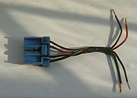 Option 2 is to
acquire a genuine switch connector block (this is one that I
purchased from the MGF Centre). I then simply soldered and shrink wrapped the
cables from the relay as described above to the short wiring loom attached
to the plug. Option 2 is to
acquire a genuine switch connector block (this is one that I
purchased from the MGF Centre). I then simply soldered and shrink wrapped the
cables from the relay as described above to the short wiring loom attached
to the plug. |
||||||||
| 9. | With all the necessary connections made, it is now possible to test the system. Reconnect the battery and start the engine. The EPAS warning light should come on with the ignition and extinguish once the engine has been started, indicating normal operation of the EPAS system. Now press the EPAS by-pass switch. The EPAS should switch off (it will be a good deal harder now to turn the steering wheel), but the EPAS warning light should remain off. Now release the by-pass switch. The EPAS warning light will momentarily illuminate prior to switching off again, indicating that EPAS is functioning normally; the steering will once again be easy to turn at rest. | ||||||||
| 10. | All that remains now is to reassemble all the trim and go for a test drive! |
Will's Verdict:
With the EPAS override car feels better around roundabouts
and low/medium speed corners (fast ones are no different). But it is very nice
just to hit a button and the parking becomes a breeze
![]()
My Verdict:
I fitted the EPAS relay back in 2002, and am writing this remark in 2006, so I've had 4 years to consider whether all the effort of fitting this was worth while. And the answer is yes, it is. What this doesn't do is transform the steering, but it does allow a useful amount of additional feel to come through the steering to inform you of what the front wheels are doing. This is particularly noticeable on the track; when the wheels loose grip, the steering becomes light. When the tyres are just exceeding their optimal slip angles, you can feel the treads 'crabbing' over the road surface. And you most certainly can feel more of the road's 'texture' coming through the steering. If you combine this with stiffer subframe bushes, the body stiffening kit and a faster TF steering rack, the overall impression is much more positive.
How do I use my car every day? In reality, I usually leave EPAS switched on - it's far more convenient to do this (I'm clearly lazy!). But for track or fast road work, it is great to be able to switch the EPAS off for the additional communication you get from doing so. The convenience of the switch also means that when one comes off from the track, you can switch EPAS back on to enable easy pit lane manoeuvring (see, I told you I was lazy!!!).
|
Rating |
|
So, yes, I would recommend this modification. It's easy and it has clear benefits. Go for it.