|
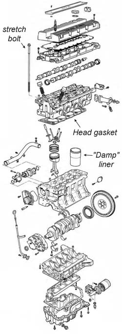
Why do Head gaskets fail? |
Outside the R&D offices of MG Rover, there are no hard and fast reasons for head gasket failure. A number of MG and Lotus enthusiasts have come up with some insightful theories however, and these are documented below.
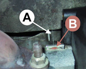 A: water jet eminating from failed gasket B: note protrusion of thin red bead of the elastomeric gasket seal |
Page Contents: |
Normal operation of the cooling system.
Quoted from the MGF workshop manual:
|
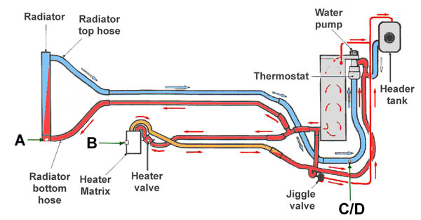
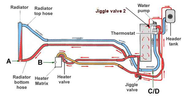
Locating the thermostat in the inlet, rather than the outlet side of the system provides a more stable control of the coolant temperature in the engine. When cold, the thermostat closes off the coolant feed from the radiator outlet. Coolant is able to circulate through the bypass and heater circuits, returning back to the engine via the thermostat bulb. As temperature increases the thermostat gradually opens, bleeding cool fluid into the cylinder block and allowing hot coolant to flow into the radiator, balancing the flow of hot and cold fluid to maintain temperature. As the thermostat opens further, so the full flow of coolant passes through the radiator. Any excess of coolant created by heat expansion is returned to the expansion tank via the bleed line. A jiggle valve fitted at the start of the bleed line, prevents pressure build-up in the expansion tank by regulating the amount of returning coolant. The coolant circulating pump is a rotor type drawing coolant directly from the thermostat, the pump is driven by a geared pulley from the camshaft timing belt.
The radiator positioned at the front of the vehicle, is a copper/brass [later to be replaced by aluminium on the TF - Ed] cross-flow type with moulded plastic end tanks. The radiator is mounted in rubber bushes; the bottom of the radiator is located in the front body member, and the top is located in the bonnet locking platform. The hoses connecting the radiator to the engine run underneath the vehicle. Three bleed points are provided for bleeding the system. For additional air flow through the radiator matrix, usually
operational when the vehicle is stationary, an electric cooling fan is fitted to the rear
of the radiator. The temperature of the cooling system is monitored by the ECM
[Electronic Control Module - also known as MEMS: modular electronic control
system] via signals from an engine coolant temperature sensor mounted
in the cylinder block outlet elbow. When a temperature of 102°C is reached, the ECM
switches the fan on via a relay. The fan switches off at 96°C. |
Is there really a problem then?
 |
The answer to that is unfortunately, yes. A web site, started by Dirk, has been collecting HGF information for a number of years now, as it first became apparent that MGF owners were suffering from head gasket failure (HGF). This is now run by MG fanatic, Mike Barnes, and can be found at http://www.shame.4mg.com. (October 2002 summary is shown opposite).
As can be seen, early cars, from the first three and a half years of manufacture, are at a very high risk of HGF. However, 1999 appears to be the year where the problem has been turned round.
We know that in 2000 a new design of head gasket and cylinder head location was introduced. However, the cause of the step change observed with 1999 built vehicles is not known.
Unfortunately this database has not been maintained beyond
2001, so whether the rates of HGF reporting have significantly altered is
unknown from this small, but independent source of reporting. To the best of my
knowledge, more detailed figures have never leaked out from MG Rover or MG Motor
UK.
Inadequate location of the cylinder head on the engine block
 A
leading cause of repeat head gasket failure on Rover T-series engines was due to
technicians apparently dropping the cylinder head fitted with a steel location
dowel onto the fresh head gasket - so the simple solution here was to replace
the steel dowel with a plastic one, and the problem was much reduced.
A
leading cause of repeat head gasket failure on Rover T-series engines was due to
technicians apparently dropping the cylinder head fitted with a steel location
dowel onto the fresh head gasket - so the simple solution here was to replace
the steel dowel with a plastic one, and the problem was much reduced.
In fact, it seemed such a good idea, that plastic cylinder head location dowels made a re-appearance on the K-series... but this engine, unlike it's earlier forbearer had an alloy, not an iron cylinder block. Only early (pre-1998) MGFs had plastic head dowels (arrowed, pictured left - one of a pair: one each end of the block). The vast majority will have had them replaced over time, but when working on an early MGF, it may be worth thinking "what dowel is used on this engine" because Rover identified the plastic head dowel as an important contributor to premature head gasket failure, and it wasn't long before all dowels were replaced with steel items on the production line and whenever an engine came in for warranty repair work.
It seemed that the plastic dowel permitted too much movement of the cylinder head relative to the engine block, causing the elastomeric beads on the head gasket to roll, peel and fail.
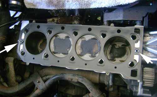
Both steel dowels are shown, arrowed, above, with a later MLS gasket fitted. Unfortunately more securely locating the cylinder head did not completely cure the head gasket endemic. Something else is at play...
So, if the thermal control of the cylinder head and block is so stable, why do HGFs occur?
One potential explanation has come from discussions with Simon Scuffham (scuffham@globalnet.co.uk) on the Elise forum regarding thermal shocks. Essentially, the cooling system is not as stable as the workshop manual would lead us to believe...
The thermal shock theory of Head gasket failure:
As Simon has found from racing his Lotus Elise (same power train as the MGF), the problems associated with the standard cooling system become more apparent the more power enhancing modifications that are performed on the engine.
The issues involved can be summarised as the following:
- The radiator has a larger cooling capacity than the engine requires (at least in northern Europe!).
- The radiator is located some pipe distance away from the engine.
- The thermostat is located on the intake to the water pump and therefore relies on the coolant by-pass to give it hot water to open.
These issues combine to cause the thermal cycling/ oscillations by the following mechanism:
- Water returning from the radiator is so cold relative to the by-pass, it inappropriately closes the thermostat.
- The engine in the meantime is still working hard and getting hotter.
- However, the thermostat takes some time to open as the by-pass return coolant needs to warm the coolant at the thermostat, causing the engine to run too hot.
- The thermostat then opens completely, dumping a bolus of cold water into the block/head.
- Repeated cycles of hot/cold thermal cycling leads to the deterioration of the head gasket (at best!).
Simon's solution is to remove the standard thermostat from its
original location and remove (or block) the by-pass. Obtain from your nearest motor
factor, a remote thermostat with by-pass (used on some Rover SD1's (2600 models), BMW's
etc.) and splice this into the outlet hose from the engine as the heater hose splits off
and use the by-pass to feed the heater.
If you have an engine generating well in excess of 200 bhp and subject the car to
track/race use then you should look at putting the thermostat at the front of the car with
the by-pass connected back into the radiator return pipe. This solution gives a much
larger volume of water at engine temp, the downside is that warm up time is much
increased.
Using the latter solution, Simon says: "I use a 87C thermostat and no matter what I
do the engine [temperature] will sit at 87C."
A more detailed explanation of the above from Simon Scuffham can be found
here. Interestingly, more recently further evidence of thermal
oscillations has been presented by Dave Monk (read
more here)
Simon was scathing about the potential benefits of drilling the thermostat ring that is
discussed below: "drilling the thermostat is NOT a solution, as it makes not a jot of
difference to the problem, it just moves the start point." Thus the thermal cycling
continues to occur, albeit from a cooler starting point, reducing the magnitude of the
thermal fluctuations.
QED incidentally already retail their own solution to this problem, bolting a replacement
thermostat on the engine outlet. It consists of an alloy thermostat holder with bleed pipe
that fits onto the hot outlet hose from the head with the bleed to the expansion bottle.
The by-pass is then blocked off, thus the water HAS to go though the new thermostat.
Nothing wrong with this approach except you loose the heater until the thermostat opens.
See http://www.qednet.demon.co.uk/
for more details.
These hypotheses are supported by K-series tuning guru, Dave Andrews...
"
As mentioned before, HGF failures are attributable to an unfavourable temperature gradient either side of the thermostat. This is due in the most part to overcooling via the long radiator run. This is not a new phenomenon; it has been experienced in just about every powerful mid-engined car.
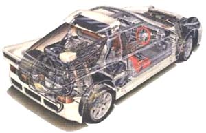 |
"The remote thermostat solution was implemented in the 1980s on the Ford RS200 rally
car, which had a mid mounted Cosworth BDT turbo producing 400BHP+. The cycling effect in
the cooling system destroyed a few engines before Hart moved the thermostat to a remote
location. This has been common practice on many mid engined cars since.
"Drilling the thermostat does lessen the cycling problem to an extent and we
have data captured from thermo-couples in the cooling system to show its effectiveness. It
is not a complete solution however.
"The coolant temperature cycling is also quite hard on the front liner....."
Simon's modified thermostat arrangement has been adapted for the MGF by Carl in Sweden, with very encouraging results. These mods are outlined on Dieter's page at http://www.lame-delegation.de/mgf-net.de/thermostat/Water_System_Mods.htm
Simon's original description can be found here.
... and by K-series aficionado, Simon Erland (speaking here in respect to the Lotus Elise, but relevant for MG owners too):
What is the cause of "so called HGF" in the K series? Well it is a complicated issue, there are many contributing factors, but the main cause is the distortion the aluminium engine suffers under the thermal gradients that occur particularly during warm up and warm down cycles. The original stat design was designed for a low weight/ max economy/min emissions vehicle, not a mid-engined sports car such as the MGF or Lotus Elise. The solution to this issue was the PRT stat , fitted as standard to many MG Rovers from 2003 onwards (particularly the TF and the Rover 75 - Ed).
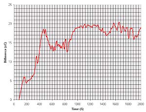 The temperature difference between the inlet and outlet of the K-series using the standard thermostat during warm-up. Not what you'd call a stable rationship. Read more on Dave Monk's measurements and developments on the MGF here or clicking the above figure. |
With the original stat, water temps were so badly
controlled that at warm up and warm down particularly, a 60 degree Celsius temp
gradient can be measured over the engine between cylinders 1 and 2. (This can
to some extent be seen in Dave Monk's telemetry experiments - see figure
opposite. He found that inlet and outlet temperatures did not have a
particularly stable relationship during warm up with some alarming temperature
spikes. You can read more about this work
here. - Ed) This
causes water to leak down the church window between 1 and 2 on the exhaust side
, causing small air pockets in the head and consequently overheating. The water
loss is insidious, but so small it burns off in the oil without being
noticeable.
Why does this small phenomenon affect the gasket? - it doesn't. It affects the
head. K is special, it was designed as a stand out engine, throwing all
conventional practice aside, most of it's features came straight from F1 design
- it was to be a ground breaking engine like the all ally bonded chassis it was
designed for - ECV3 (this is not exactly true - see article written by
someone on the ECV3 development team here
- but we'll let Simon off the hook on this one - Ed). So it had the
immensely stiff crank carrier design when, for instance, the Japanese have only
just caught up, until the k20/FOC20/ VVTI all their engines relied on the old
fashioned bearing cap design. Hand in hand with the new 4 cylinder design went
the choice of material. LM25 is a very expensive alloy, the only other mass
produced engines to use it up till now are all of Aston Martin's recent engines
and AMGs engines For Mercedes. All BMWs Hondas, Toyotas , Fords etc are made of
cheap 226. LM25 is much stronger - so you use much less of it to get the
required mechanical strength. About 40% less - hence the weight advantage of the
K compared to the "Industry standard " engines, but in order to get that
strength LM25 undergoes a heat treatment - a quench. That treatment gives it
it's strength but is also it's Achilles heal. If the operating temperatures and
hence the temperatures the engine sees are not carefully controlled, the metal
loses it's quench, it's hardness and goes soft - and over a period of time the
fire ring frets it's way into the head surface. This results in a loss of
clamping force, allowing cylinder gasses to escape and pressurise the coolant
system, forcing water into the cylinders and oil, and oil into the water - and
that's when you get the classic symptoms of "HGF". The reality is that failure
is a slippery slope and occurs long before symptoms become visible.
The gasket may go on to get hot and elastomer come free from the core plate, but
that's a secondary failure. The head is what fails, and once it is soft
no amount of new gaskets or skimming will ever prove more than a short term
prop. The head is dead. Only a new hard head can redeem failure, together with
of course, fitting of a PRT (Pressure Relief Thermostat - read more
here - Ed).
The new MLS gasket (Multi Layered Steel Gasket - read more
here
- Ed) was never a solution to "HGF," it was however part of a number of new
measures that helped the engine survive the stresses it underwent in use. The
new gasket is if you like, a bigger fuse, but the problem is the uncontrolled
temp gradients that occur with the original stat location. The remote stat is an
improvement, and the PRT works very well.
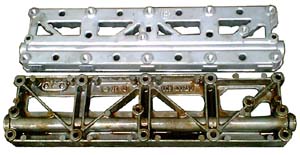 Landrover, or 'Euro4' oil rail top, compared to original item below. Picture thanks to Dr Dave @ MGRover.org forums |
Far more significant was the introduction of the revised
oil rail for Euro4 engines and now available through Landrover as a retrofit.
This new casting is a stiffer design made in ANSI357 alloy - the same metal as
F1 blocks and is as stiff a cast alloy as you can currently make. The purpose is
to resist the bending forces the engine is subjected to in those warm up/down
cycles. During all the elaborate stress analysis done on the engine in the last
5 years the original oil rail was found to collapse at the towers that hold the
bolts and allow the coolant leakage that will eventually destroy the head.
Consequently fitting the new rail is almost as important as fitting PRT. However
it is ESSENTIAL to fit it, if a MLS gasket is being used, because the new MLS
gaskets achieve only 75% of the clamping of the old elastomer gaskets [the
elastomer compresses more than the 5 steel core plates of the MLS] and
consequently the MLS is much more prone to leak than the elastomer gasket
without the new oil rail, particularly without a PRT fitted.
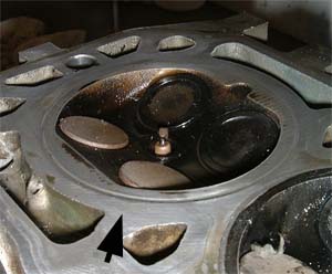 This is what my cylinder head looked like after a spectacular HGF. Pale valves are the hot exhaust valves, and the indentation in the cylinder head (arrowed) around the combustion chamber is clear to see - yes, that surface should be completely flat! Ed. |
Consequently no head should be fitted without a hardness
test. New heads register 110-120 Brinnell, I would never use one less than 100
Brinnell, less than 95 would be foolish. Most of the heads I have collected here
from failed engines have hardness ratings between 70 and 80. On failed cylinder
heads following HGF, clear indentation rings are often to be seen on the exhaust side (and
therefore hottest side - Ed) of the cylinder head where the fire ring had
pushed into the head and therefore has consequently leaked cylinder pressure (see
picture opposite - this is from my own engine following an alarming HGF blow-out
last year... ouch! - Ed).
Why is this an Achilles heel? Well 226 alloy, as used in all other 4 cylinder
petrol engines, is not a heat
treated alloy - it doesn't matter (as much) if it gets hot. There is no heat
treatment to destroy. Ergo - by virtue of material choice, the K-series is
rather more vulnerable to temperature damage than the majority of other engines
- and therefore more likely to write off the cylinder head in the event of a
HGF.
A classic mistake made in the UK was to weld up heads around the fire ring. As
we've already established that excess heat is the last thing that a quenched
LM25 alloy cylinder head needs in terms of maintaining its surface hardness, it
is clear that welding is possibly the worst thing anyone could do to a K-series
head; a head so treated is sadly practically guaranteed to fail in
short order! So beware dodgy eBay adverts!
Hope this helps explain some of the intricacies of the K series, and how and why
head gaskets can fail on these engines. - Simon
Oil temperature as a potential cause of HGF:
It has been suggested that HGF maybe more likely in cars
running with high oil temperatures.
Why?
Because of the following reasons:
- HGF is caused, at least in part, by the movement of the cylinder head over the block, which causes the head gasket's rubber beeding to fail through shear stress, and thus lead to escape of coolant.
- This movement is caused by engine block twisting under high torque loads, and also - the import bit for this discussion - due to differential expansion due to different temperatures in the head and the block.
- The cylinder head is primarily cooled by water. The block is primarily cooled by oil.
- Under high loads, the engine temperature increases (more work, more heat). This heat is disappated by the oil and water circulation. Oil is cooled by heat radiation into the airflow under the car (marginal in a mid-engined vehicle) whilst water is cooled by the radiator; water cooling here is much more efficient due to that large air/water heat exchanger known as the radiator.
- If the engine is working hard, the oil temperature will continue to rise, whilst, due to the opening of the thermostat, the water temperature is reduced.
- Water temperature is lower than the oil temperature. This means that the cylinder head is cooler than the cylinder block: the block and the head will expand at different rates = shear stress on head gasket.
- Temperature gradient problem is exacerbated when the thermostat opens and allows cold water (that has been sitting, being cooled by the airflow through the radiator) to enter the cylinder head. Suddenly, the head is even colder than the cylinder block... head contracts, whilst block expands = significant shear stress on head gasket.
So, given this premise, if your engine's oil temperature is regularly above 120ºC, the problem with differential head/block expansion is going to be significantly worse than when the oil temperature remains in the 90-100ºC range (closer to the 'regulated' water temperature).
Based on these premises, a water/oil heat exchanger may be beneficial in matching cylinder head and block temperatures, and limit the heat expansion mediated shear stress on the head gasket.
However...
There is some dispute as to the precise contribution the
water cooling plays in cooling the cylinder block. Some (including Simon
Scutham) would argue that water cooling of the block is neglible, whilst others, such
as Nick Adams (of the official Lotus Club forum)
would say that water cooling does play a significant role in engine block cooling. Thus,
both the head and the block are primarily cooled by the water, whereas the oil only cools
parts like the pistons and crankshaft. In this paradigm, the coolant system should always
run cooler than the oil and that oil temperatures above 100 Cº are actually beneficial to
the engine since they allow water and contaminants to evaporate off into the breather
system (remember that the second mark on the oil temperature gauge of your MG indicates
100ºC and not 90ºC!).
The thermal head bolt
stretch theory...
First proposed by Kes on the MG BBS:
 |
"There are some aspects of the K-series engine which
are, as far as I can tell - unique to the 'through-bolt' construction and directly affect
the head to block joint, and how well or poorly it is sealed. I'm afraid there's a lot of
it, but I'll try to be brief! I should not think that this is unknown either to MGR or to
the many specialist engineers we know and love.
"The K-series engine differs from a typical modern four-cylinder engine in that the
lower halves of the main bearings are cast in one large flat alloy housing, the main
bearing ladder. Instead of main bearing bolts being screwed upwards to hold each bearing
together, long bolts are passed down through the cylinder head and crankcase to the main
bearing ladder and pull the engine together forming a very tightly torqued-up sandwich.
The bolts are effectively main bearing cap bolts turned upside down. As the K-series
engine has five main bearings there are five pairs of bolts holding down the cylinder head
(they actually screw into a steel oil rail under the main bearing ladder, as alloy threads
would not take the huge stresses involved.) Fortunately there are additional unstressed
bolts holding the oil rail to the bearing ladder and the ladder to the block, so that the
engine won't fall apart when the head bolts are removed. There are no additional bolts on
the cylinder head.
"The following are ways in which this construction method can affect the cylinder
head to block joint.
- As the long Main Bearing/Cylinder Head bolts are trying to serve dual purposes there's a conflict. To maintain the integrity of the main bearings and to ensure that they do not distort out of round, the bolts should be as close to the bearing area - the centre line of the engine - as practicable. This leaves the bolts holding down the cylinder head in a line very close to the cylinders - in fact just about within the diameter of the bores. This is no doubt very good for clamping the fire ring around the cylinder liners, but less good for clamping any sort of seal the further away from the bolts the seal is positioned. The outer areas of the cylinder head joint are the least supported, just where the thin red bead of the elastomeric gasket seal is located.
- The furthermost point away from the head bolts, and therefore having the weakest clamping pressure, is where the head/crankcase widens at the front left and right corners of the engine. The head casting has thin walls directly in these corners as it accommodates two coolant galleries. These thin walls are more likely to distort than the more solid and more evenly clamped cylinder head. Add to this the very high temperatures on the exhaust side, then the opportunity for the head to lift at the front left-hand corner is high - possibly irresistible.
- The Main Bearing/Cylinder Head bolts are very much longer than the studs used on conventional engines to hold down the cylinder head: around 380 mm from the top of the oil rail to the underside of the bolt head. The bolts are high-tensile steel, and the crankcase and cylinder head are alloy. Both expand at quite different rates. High tensile steel has a co-efficient of thermal expansion of around 0.000012 per deg C, and alloy around 0.000024 (the exact materials used and thus their thermal coefficients are not known). The temperature rise when the engine is run will differ along the length of the bolts, but an average 100 deg rise from 10 deg C to 110 deg C will not be far out, and is probably quite modest.
- So the bolts will expand by 0.000012 x 100 x 380, which is 0.456 mm. The equivalent crankcase/head assembly will expand by 0.000024 x 100 x 380, which is 0.912 mm, almost half a millimetre more. With the threads of an ISO M12 coarse pitch bolt at 1.75 mm pitch, that's equivalent to tightening the head bolts by over a quarter of a turn each time the engine is run up to operating temperature, and then slackening them by the same amount each time it's cooled. Drive the car twice a day for 250 days a year, and that's 1500 times the bolts have been tightened and released by the time the car reaches its third birthday. Do the sums for a temperature rise of 150 deg C and the difference is even greater. This constant and repeated stretching and releasing of the head bolts must eventually result in a deterioration of clamping pressure.
- In a 'normal' engine the cylinder head is held down on the block by relatively short studs fixed in the top face of the crankcase, about 100 mm long (yes, I know, the head is actually held down by nuts screwed onto the studs). These studs are held firmly in their blind holes by being screwed down until they run out of thread and bind on the shank, or until they bind on the bottom of the tapped hole. They may also, depending on who's doing the assembly, be held tight by a thread sealant. The studs are effectively a permanent part of the crankcase. Being short, and fixed tightly, they do not flex easily. When the head is clamped down the relatively close clearance of the tunnels and the inherent stiffness of the studs holds the head firmly in place.
"The K-series bolts operate entirely differently. They are not a permanent fixture, being unbolted for head removal, so the thread fixing imparts no great lateral integrity to the bolts. In any event, the thread is a long way away from the cylinder head joint. As the bolts are 380 mm long, around three times as long as fixed studs, the bolts are more easily deflected. A 380 mm long M12 bolt, no matter how tightly held by the screw thread, or what the tensile strength, can be deflected by hand.
"The bolts are also not a close fit in the tunnels in the head or crankcase. Maybe this is because the tunnels are used as drain galleries for the oil; maybe it's because tight(er) tunnels would give problems locating the threads in the oil rail.
"For these reasons the cylinder head isn't as positively located as it would be following the normal practice of using short studs in the crankcase. That job appears to be left to the locating dowels."
The air lock theory of HGF is simply that as stated: air bubbles get trapped in the coolant circuit, arresting coolant flow.
Either through poor coolant change bleeding procedure, poor maintenance, or leaking pipe work, air can be introduced into the coolant system: it is no coincidence that dealerships invested in vacuum equipment to ensure air-free coolant changes come service time.
The coolant circuit is however designed to cope with some air: small bubbles are bleed off via one of the two Jiggle valves (see figure below: the second Jiggle valve is not well identified in the official schedules in the workshop manual for some reason, but the second valve is shown in the schematic below "Jiggle valve 2"). Simple ball-in-socket valves, these permit air to pass so that it can escape harmlessly into the expansion tank (via the small bypass pipes shown in the schematic below).
However, air bubbles can become trapped in the cylinder head, small calibre by-pass pipes or where there are tight bends to be navigated, causing blockage of water flow, and therefore localised overheating of the cylinder head. This in turn can lead to damage of the head gasket and it's ultimate failure.
 |
|

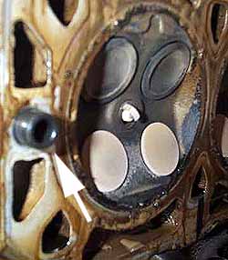
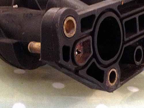 Picture
left: the jiggle valve found in the inlet manifold. The manifold shown is the
plastic inlet manifold from the 1.6/ 1.8 MPi versions of the K-series engine
found on the MGF/TF and we can see here on the mounting face (manifold gasket is
not fitted). You can see the ball-bearing valve inside the x-profile of the
coolant bypass stub pipe. If this ball-bearing gets stuck in the closed
position, it will no longer perform its de-aerating function.
Picture
left: the jiggle valve found in the inlet manifold. The manifold shown is the
plastic inlet manifold from the 1.6/ 1.8 MPi versions of the K-series engine
found on the MGF/TF and we can see here on the mounting face (manifold gasket is
not fitted). You can see the ball-bearing valve inside the x-profile of the
coolant bypass stub pipe. If this ball-bearing gets stuck in the closed
position, it will no longer perform its de-aerating function.