Weight transfer
| More reading: Brian Beckman Next / Back |
|
|
Background part one. Weight transfer
|
Weight transfer is a concept that we all probably very familiar with, even if we don't fully understand all the physics that underlies what happens when we haul up on the anchors, we all recognise the resulting movement of the car, with the front suspension hunkering down and the rear of the car rising up.
Figure 1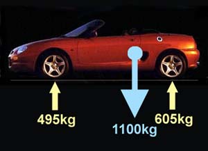 Forces acting on the car when stationary: because the car is not sinking through the ground, the upward forces acting at the wheels are equal and opposite to the weight of the car - in this case, 1100kg. Because the weight distribution is not quite equal, more weight is suspended over the rear wheels in a 45:55 distribution front to rear. |
Weight transfer, as the name suggests, is the phenomenon whereby weight appears to move forward under braking (and conversely, backwards under acceleration) - how much weight transfer occurs is closely related to where in the car the centre of gravity is located. From hereon in we are going to be using the laws of motion that were originally described by the world's most famous victim of 'Falling Apple attack', Sir Isaac Newton. Those with a pathological aversion to mathematics and physics had better look away now…
But before getting down and dirty with equations, let's envisage what happens before and then immediately after we start braking.
At a constant state, where the car is neither accelerating nor
decelerating, the weight distributed to the front and the rear wheels is in accordance to
the weight distribution of the car. So if the centre of gravity is towards the rear of the
car - as it is on a mid-engined car like the MGF/TF, then more of the weight is
concentrated over the rear wheels. In our example, 55% of the car's weight is carried over
the rear wheels - as shown in figure 1. The height of the centre of gravity is not all
that important in this state. If you were to brake from that constant speed, the rear
brakes would now be performing 55% of the work before the weight transfer starts…
Figure 2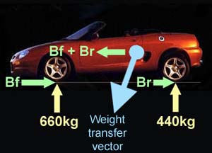 Forces acting on the car under braking. Not shown is the weight of the car acting downward in a vertical plane. As the car brakes, braking forces are applied at the front wheels (Bf) and rear wheels (Br). This force also acts at the centre of gravity (blue circle), which is some distance above the ground. The result is that the car starts to pivot over its front wheels and effectively the weight is moved forward - as shown by the weight transfer vector. If the car is able to pull a 1.0G stop, Bf+Br = 1100 x G, and by trigonometry, the angle of the weight transfer vector is inverse tan(1) - or 45 degrees... |
Now we start braking. Here, the height of the centre of gravity starts to become very important - as indeed is the wheel base and where in that wheel base the centre of gravity is located. Best way to imagine this is to take your pen as a model of a 'vehicle'. If you were to be driving your 'pen' along your desk, with the wheels located at the tip, then you have a vehicle with a very short wheel base (!) and a very high centre of gravity. Decelerate your 'pen' and it'll pivot over its front wheels and fall over as the weight transfer moves forward of the front axle line. In contrast, if the pen were driving along on it's side - so now it is a vehicle with a very long wheel base and a very low centre of gravity - braking is now very likely to pivot the vehicle over the front wheels! Okay, so these are silly and extreme examples, but essentially, these are the forces at work in your car. The lower the centre of gravity, and the longer the wheel base, the less weight transfer that'll occur. Conversely, the shorter the wheel-base and the taller the centre of gravity - the more weight transfer will occur.
Figure 3 The weight transfer vector describes how the forces apply at the centre of gravity, and how the weight shifts upon braking - at an angle of q to the vertical |
Here's an interesting observation: the weight transfer
vector is the hypotenuse of a right-angled triangle, whose opposite is the summation of
the brake forces being applied (Bf+Br - as shown in figure 2), and the adjacent being the
weight of the vehicle acting downwards from the centre of gravity (1100kg) - as shown in
figure 3. During a 1.0G stop, the decelerative force equals the mass of the vehicle,
so the angle of the force vector (q)
= inverse tan(1), or 45 degrees. If the height of the centre of gravity is 0.4m, then the
centre of gravity will move forwards in accordance to the weight transfer vector angle...
which in a 1.0G stop will be height of the centre of gravity x tan(45)
= height of the centre of gravity = 0.4m in our example... So we clearly see that the
taller the centre of gravity, the further forwards the centre of gravity moves in direct
proportion: if the centre of gravity is 0.1m, then the centre of gravity will 'move
forward' 0.1m at 1.0G. Similarly, if the centre of gravity is 1m above the ground, the
centre of gravity will 'move forward by 1.0m.
The mathematics of weight transfer.
Brian Beckman describes the mathematics of weight transfer extremely well in this link to be found on the Miata net.
So if we apply the equations (1 to 3 below) that Brian derived to the MGF, we can estimate how the weight distribution alters under heavy braking. To do this, we need to make a number of assumptions and estimations. We'll assume that the maximum rate of deceleration that a road tyre can tolerate is 0.9G. The weight distribution of the MGF is approximately 45% front and 55% rear*. The wheel base of the MGF is 2.375m*. The weight of the MGF, with fuel is approximately 1100kg. I don't know the height of the centre of gravity for the MGF, so I'm estimating that it'll be located at about a third of the total height of the vehicle - about 0.4m. So this is how this applies to Brian Beckman's equations:
Symbol |
Definition |
Estimated values for the MGF |
|
d = |
Weight distribution at front |
0.45 | |
Brian Beckman's equations: Lf=dG+Bh/w ... 1 Lr=(1-d)G-Bh/w ... 2 Lf+Lr=G ... 3 Lf is the weight load over the front wheels, while Lr is the weight over the rear wheels. |
w = |
Wheel base |
2.375m |
G = |
Static mass of vehicle |
1100kg * 9.81 = 10791N | |
h = |
Height of the centre of gravity of the vehicle |
0.4m (est) | |
B = |
Braking force |
Assume max deceleration = 0.9g thus, from Newton's law [F=ma], force = 1100x0.9x9.81= 9711.9N |
Lf=0.45x10791+9711.9*.04/2.375 |
Lr=0.55x10791-9711.9x0.4/2.375 |
=4855.95+1635.69 |
=5935.05-1635.69 |
Lf=6491.64N ~6.5kN |
Lr=4299.45N ~4.3kN |
… we see that the weight distribution following a 0.9G braking manoeuvre is approximately 60:40.
That means that for our 1100kg MG, 660kg will be loaded over the front wheel (up from 495kg under static conditions - that's like sitting a 165kg baby elephant on the bonnet!), whilst the rear wheels are loaded with only 440kg. So, for a given deceleration, from Newton's second law (F=ma), the force applied by the front wheel would be 660 x -0.9G whereas the force that would need to be applied at the rear would be 440 x -0.9G. The harder you decelerate, the more weight loading would be transferred to the front wheel, and therefore the harder the front brakes would have to work to maintain that demand.
If you were designing a brake system for this car, you therefore would want 60% of the brake force to be applied through the front wheels, and 40% by the rears. Of course, this means that under lower rates of deceleration, the rear brakes would be working at a level that is sub-optimal (recall that the rear brakes can be handling up to 55% of the braking load). It is however FAR safer to have the front wheels lock up than the rears from a stability point of view.
So what would happen if you were to install brakes that were capable of generating more than 660 x 0.9G of force at the road/ wheel interface? The balance would be disrupted. So from our 60:40 ratio, the brake ratio may instead be 70:30 or 80:20 in more extreme cases. If this happens, the front wheels would be doing all the stopping work, whilst the rear wheels would barely be working at all. And since both front and rear tyres apply retardive force, the total force of all four wheels would be LESS than if the brakes were balanced at 60:40 - result? Longer braking distances and slower deceleration. The explanation for this phenomenon is in the way that tyres generate grip, and is represented in what is known as "the Traction Circle" which is described in more detail on the next page.