Installing the Rover 820 airbox
These instructions are based on the installation of a Rover 820Efi
airbox in the MGF 1.8i using the K&N 57i as a base. These directions are equally
applicable to the MGF 1.6/1.8 Stepspeed and the TF115, and with modification to the
mounting bracket, to all the other models in the MGF/TF range. This airbox can also be
installed in any vehicle using the Rover K-series engine, although certain details (braket
dimentions, induction and downpipe lengths, etc.) will obviously be different. Any cone
filter can be used so long as it fits within the airbox casing, and equally, the airbox
can be used with a K&N filter designed to fit the Rover 820.
Parts required:
- K&N 57i kit (or similar)
- Rover 820 Efi ('88-'91) airbox
- 69 mm diameter flexible, wire supported, induction tubing (1m)
- Four jubilee clips (as found with the 57i filter kit)
- 70 mm outer-diameter collar adapter (found with 57i kit)
- Three 8 mm metric bolts and nuts, with matching washers
- 2 mm thick aluminium sheet, 200 mm x 180 mm
Tools required:
- Flat head screw driver
- Stanley knife
- Wire cutters/pliers
- 10 mm spanner or socket with ratchet
- Dremel-type cutter or junior hack-saw
- Electric drill with 10 mm bit
Time required:
- About 2 hours. Not a particularly difficult job, but some bits are a
little bit fiddly.
Instructions:
Part one: preparation of the airbox.
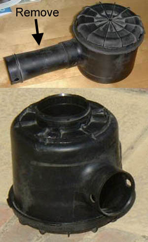
| 1 |
Very little preparation of
the air box is required, other than cleaning and disassembly. For
convenience, I chose to remove the plastic pipe extension from the airbox inlet so I had
more flexibility in positioning the airbox, although I don't think this is strictly
necessary. In fact, leaving this tube in place will save you approximately 200 mm of
flexible duct in the final 'product.' |
 |
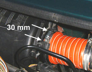
| 2 |
Take the body of the airbox
and position it as it would be located in the engine bay - i.e. with the airbox inlet
facing away from you, and the outlet to the throttle body to the right. On the outlet
flange/lip, cut away the full width of the outlet flange in a section 1.25" -
1.5" (approx. 30-40mm) wide over the top - this will enable the jubilee clip worm
drive to fit snugly up to the body of the airbox casing when completely assembled (as
illustrated, right). I found a Dremel-type cutter particularly helpful for this job. |
 |
| 3 |
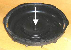
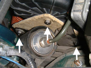
Remove the vacuum sender from
the airbox 'cap'. The vacuum sender is located in the centre of the cap, as arrowed right,
and simply pushes out. This leaves a 10 mm hole in the lid
that is used to bolt the 'cap' to the bracket and support the airbox's weight. |
 |
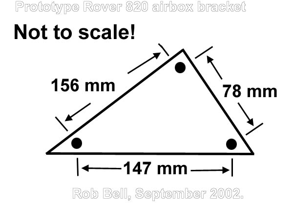
Part two: construction of the
bracket.
In the pictures, you can see that the bracket is not made of metal!
This is the prototype bracket that needs to be replaced with sheet aluminium.
The bracket is designed to utilise the existing mounting brackets
for the OE airfilter assembly, and holds the 'cap' of the airbox with a single 8mm bolt.
Use the diagram below as a template for the 1.6/1.8Mpi application
(please, if anyone constructs a bracket for the VVC, please let me have the template to
host here- thanks!). Measurements denote the hole spacings. Leave approx 10 mm of material
around each hole to edge of work piece.
Part three: preparation of the
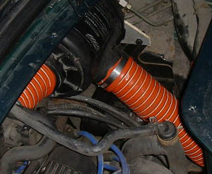
flexible hose.
You will need to lengths of hose:
- The section between the airbox and the throttle body (henceforth
known as the induction tube): length 5" (125 mm).
- The airbox cold air intake (henceforth known as the 'downpipe'):
length 27" (675 mm)
The ducts can be duct using a Stanley knife, whilst the supporting,
helical wire is cut with a pair of wire cutters. Unravel the section of wire inside the
duct ends, and cut off a further 3" (75 mm), and fold the free end of the wire inside
the pipe.
The pipe ends that meet the airbox inlet and the filter adapter tube
needs to have a short section of the external string removed (peel string from pipe, and
cut 3" (75 mm) excess with Stanley knife). This is to enable the pipe to be stretched
over the airbox inlet and filter adapter collar.
Part four: final assembly.
| 1 |
Take off the engine bay inspection cover, and completely
remove the existing filter system. If the K&N cold air pipes are present, remove them.
Completely disassemble the filter system; if you started with the K&N 57i kit, you
should end up with three jubilee clips, an adapter collar, a cone filter as well as a now
redundant rubber induction tube and two cold air ducts. |
|
| 2 |
Install the fabricated airbox
bracket to the existing bracket in the engine bay (you'll find the fuel filter is attached
to it). Use two 8 mm bolts, placing washers over the rubber 'eyes' in the bracket mounting
holes. Firmly tighten. |
 |
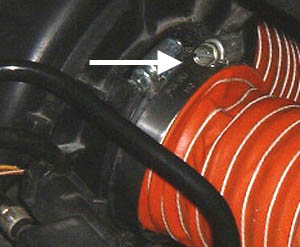
| 3 |
Bolt the airbox cap to the
mounting bracket using the single 8 mm bolt and nut, with washer on the bracket side; have
bolt protruding from the airbox cap outward, so that the nut is tightened on the bracket
side. |
| 4 |
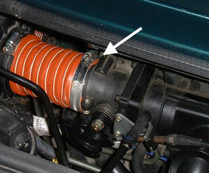
Attach the induction tube to
the filter adapter collar. The collar has a slightly wider diameter than the pipe (70
versus 69 mm) - hence the need to remove the section of support string and wire from the
pipe (as discussed in part three above). Stretch the pipe's end over collar, and fix with
jubilee clip. |
|
| 5 |
Attach downpipe to the airbox
inlet - again, the diameter of the inlet is larger than the pipe, so stretch over and fix
in position with jubilee clip. |
|
| 6 |
Insert the K&N filter
inside the airbox. The filter's outlet will fit snugly inside the airbox's outlet. When
the airbox is assembled to the cap, the filter should be kept in that position.
Unfortunately, there is a small glitch here: the K&N is fractionally too short to stop
all movement inside the airbox. This is not too much of a problem however, and can be
remedied by using a little bit of packing between the cap and filter to ensure that the
filter is kept firmly in place inside the airbox when the cap is snapped on. |
 |
| 7 |
Now offer up the adapter
collar - push fit this into the filter outlet, so that the worm-drive of the jubilee clip
fits up snugly with the body of the airbox in the indent cut out described in part one.
You may find that the collar falls out (the K&N is usually fixed onto the collar using
a jubilee clip that can't be used here). To remedy this, another jubilee clip can be used
on the outer part of the airbox outlet flange, to keep the adapter collar in position. |
| 8 |
Snap the airbox onto the cap.
This clamps the filter in position inside the airbox. Ensure that the airbox inlet and
down pipe are pointing forwards and downwards in the engine bay. |
 |
| 9 |
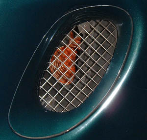
Slip a jubilee clip (or more
preferably, the OE Rover snap-clip to avoid distortion of the plastic throttle body) over
the induction tube. The tube can now be slipped over the throttle body inlet and fixed in
place. This is best accessed from the boot, with the grille removed. |
 |
| 10 |
Now guide the downpipe down
the back of the engine bay's bulkhead - push the downpipe towards the space under the
resonance box (if fitted). From the wheel arch area, the pipe can be directed into the
space behind the left hand side (nearside, RHD) air vent grille. |
 |
Job complete: replace engine inspection cover and engine bay grille
and go for a drive!
HOME