|
Words: Rob Bell |
|
This page contains: Introduction | The Problem | Turning a corner | Vortex Generators |
|
|
Side Air Intake
Aerodynamics
|
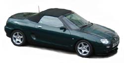 The engine bay air intakes. They look absolutely great
don't they? Doesn't matter whether you are looking at the original MGF, or its
sharp-suited replacement, the TF, the engine side air intakes look very
purposeful, and emphasise where the engine is located: in the middle of the car.
But perhaps surprisingly, these air intakes are not particularly well utilised
on the mid-engined MG. The right side intake (off-side, driver's air intake on
right hand drive cars) is used to help cool the engine bay, with an electric fan
to help force air into the enclosed compartment to aid cooling when the car is
stationary. The other side
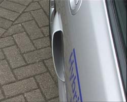
isn't actually used for anything - and indeed on early MGFs (like mine pictured
to the left), it is actually
effectively blanked off by the resonance box used in the convoluted standard air intake system...
The engine bay air intakes. They look absolutely great
don't they? Doesn't matter whether you are looking at the original MGF, or its
sharp-suited replacement, the TF, the engine side air intakes look very
purposeful, and emphasise where the engine is located: in the middle of the car.
But perhaps surprisingly, these air intakes are not particularly well utilised
on the mid-engined MG. The right side intake (off-side, driver's air intake on
right hand drive cars) is used to help cool the engine bay, with an electric fan
to help force air into the enclosed compartment to aid cooling when the car is
stationary. The other side
isn't actually used for anything - and indeed on early MGFs (like mine pictured
to the left), it is actually
effectively blanked off by the resonance box used in the convoluted standard air intake system...
 This
seems incredibly odd doesn't it? Here is seemingly a very useful resource of
cool, dense air just going to waste! It surely makes more sense to make use of
this for an induction kit for your MG?
This
seems incredibly odd doesn't it? Here is seemingly a very useful resource of
cool, dense air just going to waste! It surely makes more sense to make use of
this for an induction kit for your MG?
Well, I am inclined to agree with this - and as pictured opposite, right, is exactly what I did do with my home-made induction kit, using a Rover 820 air box. But there are problems...
These problems are worse with some air induction kits than with others. There are a variety of air filter induction kits on the market - one of the most popular is the wonderful-sounding K&N 57i kit - a cone filter that uses two flexible hoses from under the car to 'scoop' cool air and 'blow' it around the area of the air filter. This set up works well if the ends of the 'scoop pipes' are mounted as intended, under the floor pan of the car. But some folks are tempted to go for what appears to be a far neater solution: route those ducts behind the near-side (left side) air intake.
Unfortunately, as we shall see, this is perhaps not the ideal solution that we're looking for... the engineers working on the MGF knew what they were doing where it came to neglecting the air intakes. They knew that they don't in fact work...
What's the problem?
 Many
moons ago now (I've had my MG far too long it seems!), the group of us who put
together the wind stop tests featured elsewhere on these pages, decided to
undertake a little experiment with some bits of shredded paper ('ticker tape'), some sticky tape (in
true Blue Peter fashion!) and went for a drive on a private road armed with a
video camera aimed out of the window of another F being driven side by side with
the test car at a speed of 50mph. Sadly this VHS video footage appears to have been lost, but the
resulting film was quite striking. The ticker tapes that we were using as
tell-tales of air movement demonstrated that the area immediately adjacent to
the grille was stagnant. In fact, the ticker tapes moved OUTWARD almost as
frequently as they did in any other direction. Almost never did the ticker tapes
actually get sucked into the so-called air intake.
Many
moons ago now (I've had my MG far too long it seems!), the group of us who put
together the wind stop tests featured elsewhere on these pages, decided to
undertake a little experiment with some bits of shredded paper ('ticker tape'), some sticky tape (in
true Blue Peter fashion!) and went for a drive on a private road armed with a
video camera aimed out of the window of another F being driven side by side with
the test car at a speed of 50mph. Sadly this VHS video footage appears to have been lost, but the
resulting film was quite striking. The ticker tapes that we were using as
tell-tales of air movement demonstrated that the area immediately adjacent to
the grille was stagnant. In fact, the ticker tapes moved OUTWARD almost as
frequently as they did in any other direction. Almost never did the ticker tapes
actually get sucked into the so-called air intake.
It was immediately obvious to all who saw the footage that
the air intakes were simply not performing as air intakes. They are, sadly,
little more than pleasing aesthetic tweaks of the rear wings... Whilst the VHS
footage has been lost, the pattern of dirt deposition on the side of my car the
other winter actually shows how the air actually flows around the air intake.
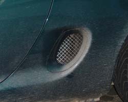
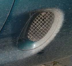 If
we look carefully at how the road grime has deposited on the wing and area
around the air intake grille, the issues of air flow
become apparent.
If
we look carefully at how the road grime has deposited on the wing and area
around the air intake grille, the issues of air flow
become apparent.
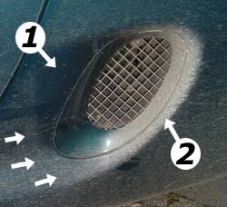
On the right is the unmolested picture, and on the left, the same image, but with the interesting areas highlighted.
Concentrating on the figure to the left for the moment, the three small arrows show the general direction of splatter of the road grime on the paint work. Must have been doing about 70mph on the motorway, as we can see the streaks are almost horizontal. What is curious, and highlighted by arrow (1), is a rectangular area ahead of the grille that is almost completely clear of road grime. Its shape fits fairly neatly into the area of the rear wing that has been recessed ahead of the grille in a stylistic move apparently designed to encourage air flow into the air intake. Clearly this is not happening: the air is detaching from the bodywork at practically the same place in the vertical plane for the full height of the air intake aperture. The air doesn't so much as reattach itself to the body work as actually smash into the trailing edge of the vent recess, as is highlighted by arrow (2). The air has completely failed to turn the corner, and instead hits the last 1/6th or so of the grille and the rear edge of the aperture, splattering this area with a dense layer of dirt. Thereafter, the air continues on its horizontal plane towards the rear wheel arch.
Oh dear. If one is relying on air flow through this grille to feed an air scoop for an exposed air filter like the 57i, then the plan is doomed to fail: you might just as well stick a sock in those intake tubes for all the use they will be in this position.
Slightly better news for those with enclosed air intake systems - at least these systems are capable of sucking in volumes of cool air and are there fore less reliant upon the natural flow characteristics of the air vent! But surely there is something that can be done to improve air flow through these grilles to benefit engine bay cooling and induction kit performance?
Getting air to turn a corner
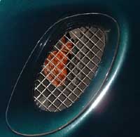
 Getting air to turn a corner is no mean feat. Rather like
water in a river, air tends to prefer to run in a straight line - so perhaps the
most obvious solution to this conundrum is to fit some form of air scoop to
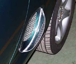
force the air into the intake. The very first modification along these lines was
made by Carl in Sweden (pictured right - and read more about it on Dieter's
website). Made of transparent
perspex, Carl has fitted an elliptical scoop that fits over the trailing edge of
the air intake trim. This effectively forces the air to turn the corner and
enter the air intake.
Getting air to turn a corner is no mean feat. Rather like
water in a river, air tends to prefer to run in a straight line - so perhaps the
most obvious solution to this conundrum is to fit some form of air scoop to
force the air into the intake. The very first modification along these lines was
made by Carl in Sweden (pictured right - and read more about it on Dieter's
website). Made of transparent
perspex, Carl has fitted an elliptical scoop that fits over the trailing edge of
the air intake trim. This effectively forces the air to turn the corner and
enter the air intake.
Carl mentions that he performed a very simple test to see whether the modification worked - he left the engine cover unbolted and drove the car - and with the intake scoop fitted, the engine bay was pressurised to such an extent that the cover was clearly lifted up! So based on this relatively crude investigation, this modification does seem to work.
Not that we should have doubts about this - after all, the engineering boffins at MIRA, who worked with MG Rover with the hybrid MG TF 200HPD, also did something remarkably similar for the TF.
The TF, despite the Peter Stevens restyle with sharper
edges and more careful attention to aerodynamics, has the same problem as the
MGF with regard to the air intakes. They simply don't work - although it is said
that the TF intakes are actually slightly better than the frankly useless MGF
items.
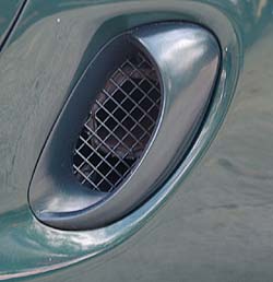
| The MIRA TF 200HPD air intakes | |
 |
 |
| Side view of the TF200HPD RHS air intake. The scoop, rather like Carl's design, attaches to the trailing edge of the intake trim. | View from above, looking downward at the intake scoop - this view shows to good effect how far this scoop protrudes from the bodywork. It is difficult to gauge scale, but I would guess it to be 25-35mm, |
Somewhat similar in principle to the intake modification performed by Carl, these scoops project about an inch (25mm) from the bodywork surface, and encompass the trailing edge of the air intake aperture. There are no figures available regarding the effectiveness of these air intake scoops (and it is interesting to note that BOTH intakes use the same scoop design, mirrored on each side of the car), but given that all the features on this concept car were designed to work and be useful, it would be a surprise to discover that these intake scoops were entirely ornamental.
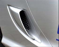
 Are
there any after market options available to buy? Interestingly, recently (early
2006), there was an eBay seller who was selling glass fibre intake scoops that
took a cue from the TF 200HPD design, but more suited to the organic MGF
bodywork shapes.
Are
there any after market options available to buy? Interestingly, recently (early
2006), there was an eBay seller who was selling glass fibre intake scoops that
took a cue from the TF 200HPD design, but more suited to the organic MGF
bodywork shapes.
Pictured opposite right, these after market scoops (described in more detail here) are designed to be bonded to the grille trim. Unlike Carl's trim, these items extend further forward top and bottom - perhaps a little further forward than the mud-streak pictures further up this page appear to indicate is necessary.
Like the MIRA intakes, there are no figures available to show the effectiveness or otherwise of this particular design of scoop - but my only anxiety is that this particular design may obscure part of the intake. That said, if it aids air entry into the intake duct, it will be dramatically better than the standard fare! These items were not particularly expensive and are worth a punt for a bit of experimentation.
Scoops are one solution. Completely redesigning the side of the car to incorporate a NASCAR duct would be another - if somewhat radical alternative. But might there be a third way?
Vortex Generators?
This is an area that has yet to be explored as a way of encouraging the air flow to remain attached to the bodywork as the flow approaches the air intake grille. Certainly vortex generators have been studied as a way to improve aerodynamic drag on the latest versions of the Mitsubishi Evo, encouraging airflow to flow from the roof over the rear windscreen without detachment (read relevant paper here). However, whether this is enough to over come the need to encourage the air flow to turn a corner as is required for the MGF duct design is an altogether different question that has yet to be addressed...
The problem with the Vortex generator concept however, is that it relies on being in reasonably clean air. The problem with the sides of the MGF and TF is that the air flow is largely disrupted by messy air flow around the front wheels and the wheel arches. Although we see evidence that the airflow reattaches itself to the sides of the body work at speed, whether this is sufficient to permit a vortex generator to work is another question; perhaps the intake 'ear' concept is the one to go for. Certainly this is what the team at MIRA believed.