|
Words: Rob Bell |
|
This page contains |
|
|
MGF aerodynamics: the engine side air
intakes
|
 The
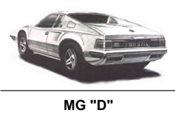
MGF was MG’s first production mid-engine roadster – but we know that MG had been
thinking about mid-engine configurations for some while; the ill-fated MGD
of the 1970s for example, and of course the 1980’s MGEXE concept
(pictured right).
The
MGF was MG’s first production mid-engine roadster – but we know that MG had been
thinking about mid-engine configurations for some while; the ill-fated MGD
of the 1970s for example, and of course the 1980’s MGEXE concept
(pictured right).
Having the engine in the centre of the car has its advantages and disadvantages of course – it’s impact on the various aspects of vehicle dynamics, packaging and costing are all worth articles in their own right, but what I want to concentrate on here is air; in particular, getting air into the engine bay, and air into the engine itself.
The flow of air...
Having the engine in the front of the car has its advantages from the perspective of air – usually you have a grille on the front of the car through which vast quantities of air can flow – cooling the engine bay, cooling the engine oil and feeding the engine’s unquenchable appetite for air to burn fuel. Putting the engine in the centre of the car means that this through-put of air is somewhat more restricted – essentially we’re putting the engine inside a sealed metal box…
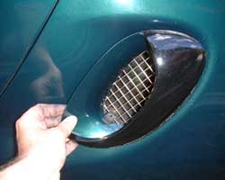
Clearly the MGF’s stylists, headed by Gerry McGovern, knew all about these problems – and decided to make a stylistic virtue out of the need for air by putting a couple of air intakes on the flanks of each side of the car. Who are we to deny how attractive they look? Look good, they do; effective they’re not…
What’s the problem?
As we’re all aware, the MGF’s gestation was undertaken on a shoe-string budget; British Aerospace (then owners of Rover Group) had other vehicle projects on the go with technology partner Honda, so could not free up significant funds for development. As a result, the MGF only saw the inside of a wind tunnel after the styling was signed off. Some bits of the car worked well (the cut-off tail for example worked rather like a Kamm-tail, and proved to be pretty effective aerodynamically). Other bits didn’t – hence the front-end aerodynamic lift and the rather ineffective side engine air intakes.
You see, air molecules just don’t want to play ball… Given half a chance, they’ll just travel in a straight line. Your car, when it travels through air, forces the air molecules to move off in altogether different directions, which it is rather loath to do – and this in part is where aerodynamic resistance stems from. Back to those air intakes: the flanks of the car curve subtly inward ahead of the intake grilles, and thereafter take a near 90 degree turn. However our linear-minded air particle wants to take a straight line – and rather than faithfully following the profile of the side of the car, the air stream detaches from the bodywork just ahead of the air intake and sails straight past the grille. This can be seen rather well when your car gets dirty - see below:
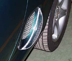
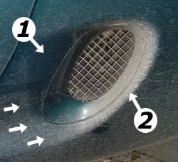 Pictured
left, the left-side air intake on my MGF – note the clean area of paintwork (1)
ahead of the grille, showing the area where the air-stream detaches from the
body – and the area aft of the grille where the air-stream strikes the bodywork
– it’s all a bit of a mess, and not at all aerodynamically effective.
Pictured
left, the left-side air intake on my MGF – note the clean area of paintwork (1)
ahead of the grille, showing the area where the air-stream detaches from the
body – and the area aft of the grille where the air-stream strikes the bodywork
– it’s all a bit of a mess, and not at all aerodynamically effective.
You can see in area marked with the (1) that the bodywork is much cleaner than the adjoining paintwork, indicating that the dirt-carrying air has come away and carries straight on over the grille, before smashing into the far end of the intake grille trim (see how dirty area (2) has become). Not good if the objective is feeding air into the engine bay.
We have more evidence too. Many moons ago now, Andy Phillips, Paul Sharpe, Tom Randell and I undertook some filming of some streamers in and around those side intakes (a technique known as wool-tufting). At 50 mph, the streamers on the grille barely moved – and if they moved at all, it was outward. As a supply of cold air for the engine bay, they are as useful as a chocolate tea-pot – and almost certainly caused some headaches for the engineers working on the MG as it slowly approached production.
A few imaginative solutions later, we have an MG that uses alternative sources of cool air to bring down engine bay temperatures (namely air flow under the car – the air is drawn up from below and discharged through vents in the upper edge of the boot lid; the engine air intake is taken from the coolest point in the engine bay, above the rear beam of the engine subframe). The side air intakes are largely decorative; the left side intake being largely obscured on the early MGF by the resonance box in the intake tract and the right intake is only used for when the car is near stationary; an electric fan being used to help drop engine bay temperatures where there is no air flow to blow off the excess heat.
Overall, this set up all seems to work – but what if you want to fit a ‘Performance’ air filter kit? The obvious place to put the air intake tube is behind that left sided air intake grille. This works well too, assuming that you are using an enclosed air filter kit, like that sold by ITG (the Maxogen) or Piper (the Viper). These enclosed kits will suck air in, and do not rely on the natural movement of the airflow.
An alternative solution?
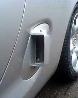
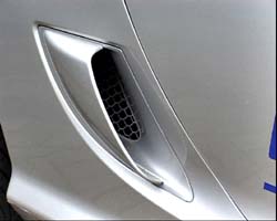 Right sided airscoop from MIRA-developed MG TF 200HPD – picture credit, Tony Hall |
But perhaps encouraging more air into these air intake ducts would help things along a bit? Certainly this is what the chaps at MIRA thought when their attention was focused up the MG TF 200 HPD. We all know that Peter Stevens’ re-styling of Gerry McGovern’s original was in part driven by the wind tunnel, but sadly the side intake ducts on the TF are only a little bit better than those on the MGF. To get air to turn the corner and through those side intakes, the 200HPD design team needed to put some scoops onto the intakes - and these are clearly shown on the picture shown right (picture credit to Tony Hall).
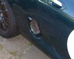
 Carl’s DIY airscoop made from Perspex screwed to the existing intake grille trim – and by all accounts a very effective solution |
The boffins at MIRA were hardly the first with this idea – as MGF enthusiast owner, Carl, in Sweden had come up with a similar solution many years previously (details can be found on Dieter’s website: http://www.mgfcar.de/ ) – and was found to be quite effective in terms of getting much more air into the engine bay to the extent that the existing vents in the boot lid were thought inadequate to let all that extra the air out of the engine bay…
If a scoop is a good idea, then how can we do the same thing? As it turns out – as is often the case in this modern age – eBay and the internet is our friend. A fibre glass styling company (http://stores.ebay.co.uk/SSPerformance-autostyling) that trades on the electronic auction site produces a pair of scoops specifically designed for the MGF.
The following section is how to fit them.
How to fit eBay glass fibre air scoops:
Tools required:
|
Materials required:
|
Time required:
|
The instructions:
|
1 |
 First off, you will need to remove the existing air intake
grilles. These are retained in place by two self tapping screws. Unfortunately,
they’re made of mild steel – and they can corrode rather badly making removal
somewhat tricky. Predictably, one of mine was completely disastrous – the
Phillips head completely disintegrating, resulting in all sorts of amusement
trying to get this last remaining fastener off. You’ve been warned. I purchased
a pack of stainless steel self-tappers from Silverstone this year in the hope of
avoiding any kind of repeat performance in future!!! First off, you will need to remove the existing air intake
grilles. These are retained in place by two self tapping screws. Unfortunately,
they’re made of mild steel – and they can corrode rather badly making removal
somewhat tricky. Predictably, one of mine was completely disastrous – the
Phillips head completely disintegrating, resulting in all sorts of amusement
trying to get this last remaining fastener off. You’ve been warned. I purchased
a pack of stainless steel self-tappers from Silverstone this year in the hope of
avoiding any kind of repeat performance in future!!!
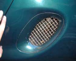
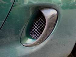
Pictured right – the standard air intake grille. Retaining screws can be seen through the stainless mesh at both the top and bottom of the grille. Take care removing the screws – they can be tricky to take out due to corrosion of the mild steel screw. |
| 2 |
|
| 3 |
To attach, simply screw the trim back on. You may find that the upper screw is now hard to get to. I had a screw driver with a 90 degree drive which I found most useful for this task.
|
| 4 |
 Here we go, job done: Here we go, job done: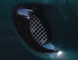 Close up of the grille – you can see the lower stainless
steel self tapper in this image Close up of the grille – you can see the lower stainless
steel self tapper in this image 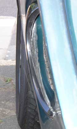 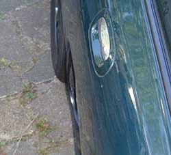 The next two images show how far the scoop extends into
the air stream – which is to say, not that far. In fact, I wonder whether these
would be better if they protruded a further centimetre or so? But as an
off-the-shelf offering, these seem to offer good value – and worth a try… The next two images show how far the scoop extends into
the air stream – which is to say, not that far. In fact, I wonder whether these
would be better if they protruded a further centimetre or so? But as an
off-the-shelf offering, these seem to offer good value – and worth a try… |
All I have are subjective impressions at the moment, as attempting to quantify whether these scoops make any difference is a little tricky – after all, trying to replicate a forward speed of 50-80mph in a standard rolling road is frankly impossible. A rolling road inside a wind tunnel would be ideal – but I am not sure that anyone outside a F1 team would have access to that kind of kit. Certainly not me.
Before I move on to my subjective impressions, I should say that I was very sceptical that these scoops would work at all – I didn’t think that they were large enough for a start, but continued to fit them anyway through curiosity. I have my own induction kit on my car (a cone filter enclosed inside a Rover 820 airbox), which draws air from the left hand intake grille – so if the scoops did indeed work, then there was a potential performance benefit to be derived.
Given that I didn’t think that these scoops were going to work, I was somewhat surprised that the engine did feel different. Broadly speaking you need a 5lb.ft torque change to feel anything from the driver’s seat, but from low speeds in particular, the car responds more cleanly and eagerly. At the top end, I don’t think that there is much of a change. This is quite the opposite of what I had anticipated! At higher speed I was expecting more benefit due to higher pressure air feeding the air filter intake, but clearly there seemed to be a benefit to air flow into the air box from much lower engine speeds (where perhaps there is not so much ‘suck’ from the inlet vacuum) and lower road speeds. To verify whether this was real or merely imagined is going to take some more testing – and some thought as to how best to construct a genuinely useful test!
 One thing that was worth looking at again was the mud
splatter – and since this is an excellent excuse not to wash the car for a
couple of months, worth doing.
One thing that was worth looking at again was the mud
splatter – and since this is an excellent excuse not to wash the car for a
couple of months, worth doing.
From the image shown right, we can see that the paintwork immediately ahead of the grilles remain much cleaner than the adjoining bodywork – much as we saw before. Given that we hadn’t done anything to encourage the air to change direction ahead of the engine air intake this is no surprise. But given the splatter over the scoops, it is clear that they are indeed in the air-stream.
In fact, what I think the scoops are doing is causing an area of air to stack up in front of them – rather like a pile of mud in front of a bull-dozer blade. This is almost certainly high pressure air, which potentially means a denser intake charge for the air filter induction kit to feed from once vehicle speeds rise.
Much of this air appears to spill over the top of the scoop.
Could the design be improved? Yes, I think so. One task would be to enlarge the scoop so that it protruded further into the air stream - although clearly this would have an adverse impact upon aerodynamic drag. The other thing that could be done would be to put vortex generators ahead of the intakes to encourage the air to follow the body work. This will be an objective for further testing.
 In
summary we have a ‘problem’ with our air intakes – they simply do not flow air
as standard. One solution that has been employed in the past is a scoop
arrangement – and here we’ve been looking at one off-the-shelf solution that is
currently available off the internet. First impressions are favourable – and
given the price, probably worth a go. As for the aesthetics, well, I’ll leave
that to you – but I personally grown to rather like them.
In
summary we have a ‘problem’ with our air intakes – they simply do not flow air
as standard. One solution that has been employed in the past is a scoop
arrangement – and here we’ve been looking at one off-the-shelf solution that is
currently available off the internet. First impressions are favourable – and
given the price, probably worth a go. As for the aesthetics, well, I’ll leave
that to you – but I personally grown to rather like them.
I do plan additional tests into these scoops’ effectiveness – and I shall report back any findings – whether they’re positive or negative!
Of course, there is nothing to stop you developing your own air scoops – and this has been done before. Below show one such effort, this time using a drain pipe angle piece purchased from B&Q! (Thanks to Fran for this picture)
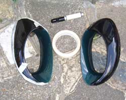 The next task is matching up the scoops to your grille
trims. The instructions on the website suggest you use some masking tape and a
bonding agent that doesn’t appear in your local Halfords. I ended up using some
epoxy resin, which is. The masking tape is useful as it stops excess adhesive
getting into places you don’t want it – and moreover, because the fibreglass
scoop isn’t quite a perfect match to the grille trim profile (or at least not on
mine!!!), the adhesive fills in the gaps left. I decided to leave mine in the
natural gloss black gel-coat, but you might want to get yours sprayed body
colour. Whether you spray before of after sticking them in place is entirely up
to you – but I would think that afterwards is probably the best approach. See
below.
The next task is matching up the scoops to your grille
trims. The instructions on the website suggest you use some masking tape and a
bonding agent that doesn’t appear in your local Halfords. I ended up using some
epoxy resin, which is. The masking tape is useful as it stops excess adhesive
getting into places you don’t want it – and moreover, because the fibreglass
scoop isn’t quite a perfect match to the grille trim profile (or at least not on
mine!!!), the adhesive fills in the gaps left. I decided to leave mine in the
natural gloss black gel-coat, but you might want to get yours sprayed body
colour. Whether you spray before of after sticking them in place is entirely up
to you – but I would think that afterwards is probably the best approach. See
below. 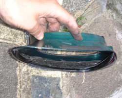 The next picture shows the inside of the scoop after I’d
bonded it to the intake grille trim – perhaps not the neatest finish, but it is
largely out of sight, and if you are fitting to your car, you can probably
finish it to what ever standard you fancy!
The next picture shows the inside of the scoop after I’d
bonded it to the intake grille trim – perhaps not the neatest finish, but it is
largely out of sight, and if you are fitting to your car, you can probably
finish it to what ever standard you fancy!