|
Words and figures: Rob Bell |
|
This page contains: Introduction | aerodynamic problem | Lift | Front radiator | Bonnet Pressures | MIRA solution | Gurney Flap | Conclusion |
|
MGTF
200HPD Aeropack - more
than just good looks
|
Introduction: the TF 200 HPD
The MG TF 200HPD represented something of a world first - a performance petrol-electric hybrid car - and certainly it is a refreshing change from the usual heavy, 4WD MPV hybrids that have been the primary concept car diet of recent years.
Of course, any article that covers the 200HPD would need to cover the clever electric technology that was invested into this car, which was largely developed by MIRA (Motor Industry Research Association - website here) with input from MG Rover - and this is covered in some detail here. However, the focus of this article is the aero package that was applied to the MG TF as part of its make over to become the 200HPD - a package that included engine bay heat management that is beyond the scope of this particular article.
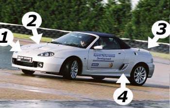
There are 4 main areas of the body work/ aerodynamics that MIRA concentrated upon with the 200HPD - and these are illustrated in the image opposite, right. (1) the upper grilles are deleted, (2) bonnet vents are let into bonnet to allow radiator air to exit, (3) the already extended TF rear boot lid gained a small gurney flap spoiler and (4) air vent scoops have been added to the side air vents (these are discussed in a little more detail here).
There are explanations for each of these modifications - but perhaps the most radical are the front end modifications, as illustrated by arrows 1 and 2.
When MIRA undertook the 200HPD project, they had a
free-hand in the final shape of the car - so there was no interference by MG
Rover over how the car finally ended up looking. This meant that the team were
able to go to town on the development of the aerodynamic package that the 200HPD
was to ultimately use.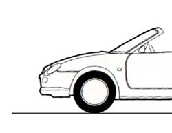
The MGF aerodynamic problem
Unfortunately, as indicated elsewhere, the MGF is blighted by a significant aerodynamic problem in the form of significant front end-lift (as described here). The ideal for a road car is to have 0 lift over the front axle. A Formula One car would have -0.8 lift, the negative indicating that active down-force is being generated.
Down force is usually avoided on road cars, as this complicates the design of a compliant suspension set up. Apply significant down force, and you will need to fit stiffer springs to stop the car from completely compressing its suspension as the speeds rise and scraping along the ground in extremis!
At the front end of most hatch back cars, designers often opt for about 0.1 lift - often as a way of encouraging a little bit of stabilising understeer in fast corners. Seems safe.
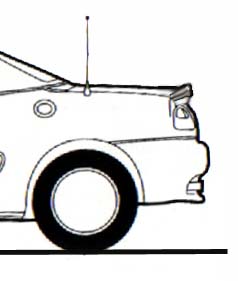
Having established that +0.1 lift is probably
what most designers and aerodynamic engineers would feel is acceptable as
normal, it is interesting to find out what figure the MGF registers (the front end of which is shown in side view in the
figure, right). Perhaps somewhat incredibly, the front lift figure of the MGF, a
car designed as recently as the early 1990s, had a front end lift coefficient of
+0.213. In other words, the front of the MGF has more than double the amount of
lift seen on practically any other contemporaneous vehicle! Clearly, this is a
sign of the rushed development and restricted resources available to the MGF
team as they struggled to bring the new MG roadster to market in 1995. Unfortunately, the MG TF is only
fractionally better - despite designer Peter Stevens investing time and effort at the
MIRA wind tunnel. However, where it came to the 200HPD project, MIRA had the
facilities and the ability to put this particular problem right - and hence the
evident unique appearance of the TF 200HPD.
The generation of lift
Let's consider what is happening to the air flow as the MGF travels along a straight road. In profile, the air is forced in one of two directions: above the car, or below the car. The MGF is certainly no different from any other car in this regard! It won't have missed your attention that the bottom of a car is almost a straight line, whereas the top of the car is more shapely - with a long curved bonnet, and a glass area above this. Consequently, air above the car has further to travel than air moving under the car. And because of this it moves faster. And as we know, fast moving air is less dense than slow moving air - so as a consequence of the pressure differential over the upper and lower surfaces (low and high respectively), lift is generated.
An aerodynamicist will be able to ameliorate these effects to a large degree by clever detail design of the front end of the car, preventing unwanted air from moving under the car and shifting this to the upper surfaces. Less air running under the car will drop the density and speed up the airflow, and therefore counter act the pressure differences between the upper and lower surfaces of the car - and hence reduce lift.
In fact this is exactly what the various splitters that
are available for the MGF aim to do - and are very successful too, as their
popularity clearly indicates.
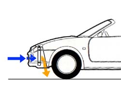
Air flow management through the front radiator
However, there is a further problem compounding the front end lift of the MGF, the position of the radiator, and more importantly, how the air exiting the radiator is ducted out (see figure right). As we well know, the MGF's front bumper has three apertures - one large one under the number plate, and two smaller grilles either side of the MG badge. TF is effectively similar, albeit with four smaller grille slats either side of the MG badge.
As shown opposite, right, the radiator sits behind these apertures - and effectively is mostly fed by the single large aperture below the number plate. Behind the radiator is the spare wheel well - which is angled. This is fairly close to the rear of the radiator, and forces the radiator 'exhaust' air downwards, such that it vents almost vertically downward ahead of the front wheels. If nothing else, this venting air will cause a lifting force (in true Newtonian style of force versus reactions) on the front axle. And that's before we consider what is happening to that increased volume of air ducted under the car from the nose cone... Needless to say that this is not an ideal solution if one wants to contain lift.
Is there another solution?
Air pressure over the bonnet
One potential solution would be to vent the radiator 'exhaust' air upwards rather than downwards. So what design parameters are there to consider?
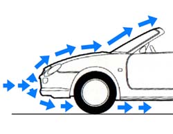
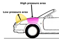
Interestingly, over the bonnet, there are high pressure areas and low pressure areas. The areas of low pressure are where the air flow is out of necessity travelling fastest - and that usually means where the bonnet is curved - which on the MGF is actually the front third of the bonnet. Thereafter the bonnet profile straightens out - and this is the area where there is high pressure - an area that is usually just ahead of the scuttle and the base of the windscreen. (An anorak aside here - Triumph 2000 rally cars put their air intake immediately ahead of the windscreen base to make use of the higher pressure air to increase the intake of cold air into the induction system of their tuned engines. Okay, I'll shut up now - Ed.)
So what we have are areas of low pressure and areas of high pressure over the bonnet (as shown in the figure opposite - orange for the low pressure area, and magenta for the high pressure area). When considering where to place a radiator exit, it makes sense to make use of the low pressure area over the bonnet to effectively 'suck' the radiator exhaust air out - and in doing so, means that you can get away with a smaller bonnet vent area. And a smaller vent has certain aesthetic advantages, and probably other issues too... not least rigidity of the bonnet pressing!
We have already established that the low pressure area
over the MGF bonnet is over the front third of the bonnet - so this makes the
most sensible place to put our radiator exit vent - so it is no surprise to
discover that the TF200HPD vents are in precisely this position...
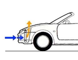
The MIRA radiator outlet modification
To take advantage of this low pressure area on the bonnet, the radiator outlet needs to be modified - which unfortunately means the loss of the standard spare wheel well (and possibly one reason why neither the MGF nor TF got this modification in production). By reversing the slope of the panel behind the radiator, and blocking the under body radiator vent, all air is now forced upward and through the bonnet - air movement aided by the low pressure area concentrated over this part of the bonnet.
This solution cuts the down-jet of air that threatens to
lift the front of the car, and reduces the amount of air that can stagnate in
its journey under the car... Plus, of course, the low pressure area will not be
at such a low pressure due to the feed of additional air into this zone. In any
case the result is dramatically less lift over the front axle.
More benefits!
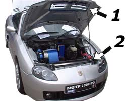 Under the bonnet of the 200HPD: (1) shows the new vents let into the bonnet, while (2) shows the radiator exhaust vent, trimmed with a rubber gasket. Neat job. |
In fact, this is not where all the advantages end. The standard MGF and TF radiator is huge. Its is necessarily large because, as the chaps at MIRA found out, only the bottom 20% or so of the radiator is being effectively utilised. Which is not entirely surprising when you look at the standard air flow through the radiator - with little space behind the top of the radiator, there will be little air passing through this part of the heat exchanger. Plus, as all the air is being forced downward, there will only be decent air flow through the base of the radiator! Following the bonnet vent modification, MIRA found that the radiator was dramatically more efficient. So much more efficient that, despite the increased demands being placed upon the engine by the electrical equipment, the radiator's size could be cut by half!
And because the radiator was getting more than enough air from the lower aperture in the nose cone, the top radiator apertures were surplus to requirement and could be deleted. Which means less drag.
In fact, the modifications were so effective that the
coefficient of drag was slashed by 10% - so aiding the top speed (although I
wasn't told what the new top speed was for the 200HPD!).
 Gurney
Flap
Gurney
Flap
We've discussed front end lift all the way through. And remember that the standard MGF had lift of +0.2. The aim for the 200HPD was 0 lift - and this is exactly what they managed to achieve. Which is an absolutely massive difference, and a real credit to the team involved.
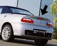 To
balance this markedly diminished lift at the front, a 25mm Gurney flap was added to the TF's
boot lid, so that lift over the rear axle was also 0 (as shown in the figure
right, and the TF200HPD picture, left).
To
balance this markedly diminished lift at the front, a 25mm Gurney flap was added to the TF's
boot lid, so that lift over the rear axle was also 0 (as shown in the figure
right, and the TF200HPD picture, left).
This body kit has yet to be replicated for public consumption - and one wonders whether the research pioneered by MIRA is familiar to the new owners of MG - but without doubt, with zero lift over the front and rear axles, the TF would be a far better drive, especially at any speed over 50mph - the point at which the steering effort seems to drop quite noticeably... I for one certainly hope that MG's new Chinese owners do take note - and consider making the change to the next generation of MGs due to roll out of Longbridge in 2007.
The MIRA developed 200 HPD aerodynamic package resulted in quite dramatic improvements in terms of aerodynamic lift - to the extent that steering loads at 100mph are much the same as they are at speeds little over 10mph. Moreover, these modifications could readily apply to the earlier MGF as they clearly do for the MGTF.
I predict a demand for a kit based upon the impressive 200HPD - although how many people would be brave enough to cut open their bonnets and loose their spare wheel? That I don't know - for unlike most body kits, this one represents rather more than bolting on bits of glass fibre and adding a bit of body filler...