|
|
How to replace a rear Hydragas sphere without dropping the rear subframe
|
|
This page contains: |
Introduction | Replacement options | Frequently asked questions | How to replace the hydragas sphere | Conclusions |
|
Replacement options At the time of writing, replacement rear hydragas spheres are almost non-existant as new old-stock original MG-Rover parts (Dunlop closed their manufacturing plant in 2001), and alternative spring-based replacement units from Suplex are just hoving on the horizon. However, even if Suplex springs are available, they would necessitate replacement of the whole Hydragas system complete with new, replacement matched dampers. Some original Trophy specification hydragas spheres do remain available, but again, this is only an option if you replace all four spheres at the same time; they have different spring and damping characteristics to the ‘standard’ hydragas sphere. Therefore, replacement hydragas spheres will invariably be second hand – either from a breakers yard, or off our favourite internet auction site. Buyer beware. |
Fortunately, the hydrogas suspension is a very reliable system with failure of the individual suspension units being very rare. However, failures can and do occur – which can be due to damage to/ fatigue of a rubber membrane or to loss of nitrogen gas (more here). Rubber membrane failure necessitates replacement of the affected hydrogas unit. For a number of reasons, failure is almost invariably of a rear sphere – which occurred on my MGF recently. In this web article, I shall show you how I replaced the rear hydragas sphere without dropping the subframe.
Frequently asked questions:
FAQ1: Can front hydragas spheres be used as a replacement for the rear?
As
new standard hydragas spheres remain available (probably reflecting the lower
failure rate of these spheres in this position), it is tempting to fit these to
the rear of the car. Outwardly, at first inspection, they look identical. But
they’re not; the shape of the displacer sphere is different, lending the
suspension unit a very different spring and damping characteristic. So the short
answer is no, you can’t use front hydragas spheres to replace the ones at the
back.
 FAQ2: How do I diagnose suspension failure?
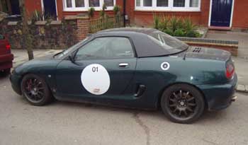
How do you know you’ve got a problem? Hydragas suspension systems have a
habit of dropping over a period of time, so if you find that the car is on the
low side, but the car is equal from one side to another, then there probably
isn’t anything to worry about, and all it needs is a simple pump-up with fresh
hydragas fluid. Serious trouble is usually indicated by a rapid loss of ride
height (may be over a period of days or weeks), effecting one side rather than
both (as pictured here, right), and perhaps one corner in particular.
If the mode of failure is complete rupture of the rubber diaphragm, then tell-tale evidence of dripping green hydragas fluid may be in evidence (see Dieter’s webpage here). Unfortunately however, fluid loss may be rather more insidious. A slow leak can be retained by the hydragas units lower dust cap, retaining the hydragas fluid from being exposed to the outside world – and in this case, only direct inspection can reveal the problem.
How to replace a rear Hydragas sphere, without dropping the subframe
If you are able to drop the subframe, then this is the ideal approach because it makes removing the Hydragas sphere a doddle. However, this does require lifting the rear of the car, and undoing the subframe mounts. This would not be too much of a problem but for the body mounts apparently being made of a material akin to a Cadburys Crunch bar; they shear off as soon as you attempt to undo them. Therefore, leaving the subframe alone is desirable, unless there are other jobs that also need attending to (good opportunity to do a cam belt change; so much easier when the engine is out of the car!).
| Tools required: | Materials required: | Time required: | ||
|
|
|
|
1. |
Place jack under car and lift, with opposite wheels chocked to prevent movement. Getting a trolley jack under a car whose suspension is completely depressurised can be very difficult, so you may find it helpful to start raising the back of the car with the standard car tool kit scissor jack (I put mine under the rear subframe). Once raised, secure on axle stands. You may find it useful to have loosened the wheel nuts before lifting the rear wheel completely off the ground, so that the nuts are just finger tight, and then remove road wheel once the rear of the car is off the ground. Fully depressurise the hydragas system on the side of failed unit, and apply some vacuum. Chances are the system will fail to hold a significant negative pressure, confirming a failed rubber membrane. |
|
2. |
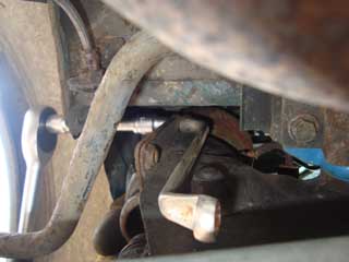
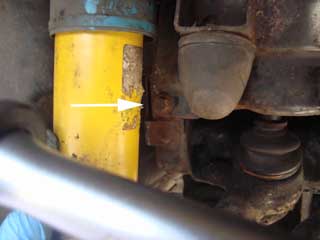
The reason for removing these engine bay components is to improve access to the rear of the hydragas unit, and particularly the rear hydragas hydraulic union (arrowed in picture, right).
Some hydragas fluid will leak out at this stage – no problem, but you could strategically place some paper towels to pick up the released fluid. |
|
3. |
Now move to the wheel well. Undo and release the lower damper mount. This will allow the damper some movement from side-to-side. You could also remove the top mounts. On a car with standard dampers, this can be un-bolted from the top. I use a leather-strap type oil filter wrench to prevent the damper housing rotating when undoing the top mount. With these Bilsteins, I left them in place as there is just enough room to smuggle in a 10mm socket on a ½" drive extension to the top left mounting. |
| 4. |
 Now we can move to release and remove the outer Hydragas sphere retaining
bracket. It is held in place by four 10mm head bolts. The lower two are
screwed into captive bolts. Unfortunately the upper two are into loose nuts.
This is a little annoying, but the upper left 13mm nut is accessible from
the engine bay, and the upper right from under the car (as pictured, right). For the former, I
used a 13mm cranked ring spanner, which held itself in place as you undo the
bolt. For the latter, I used the same tool – which again, will swing round
to lodge itself to enable you to easily undo the bolt. Now we can move to release and remove the outer Hydragas sphere retaining
bracket. It is held in place by four 10mm head bolts. The lower two are
screwed into captive bolts. Unfortunately the upper two are into loose nuts.
This is a little annoying, but the upper left 13mm nut is accessible from
the engine bay, and the upper right from under the car (as pictured, right). For the former, I
used a 13mm cranked ring spanner, which held itself in place as you undo the
bolt. For the latter, I used the same tool – which again, will swing round
to lodge itself to enable you to easily undo the bolt. |
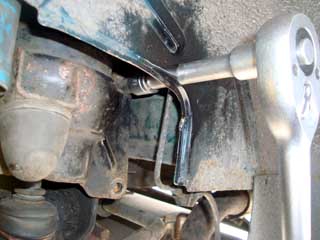 Access to the top right bolt was the most troublesome – and on my car,
was particularly tight. A 10mm ratchet spanner had insufficient leverage,
and I began to fear for the ratchet’s mechanism, so in the end, I drilled a
hole through the wheel arch. A 16mm hole was just sufficient to poke through
a ¾" drive extension onto a ¾" drive 10mm socket (as pictured,
right). If you wish to do the
same, be wary: there is a metal brake line in this immediate vicinity, so be
very careful. Once drilled, it made undoing this particular bolt very easy. Access to the top right bolt was the most troublesome – and on my car,
was particularly tight. A 10mm ratchet spanner had insufficient leverage,
and I began to fear for the ratchet’s mechanism, so in the end, I drilled a
hole through the wheel arch. A 16mm hole was just sufficient to poke through
a ¾" drive extension onto a ¾" drive 10mm socket (as pictured,
right). If you wish to do the
same, be wary: there is a metal brake line in this immediate vicinity, so be
very careful. Once drilled, it made undoing this particular bolt very easy. |
|
|
The bracket will now fall out of the way.
|
|
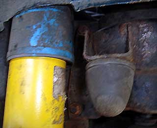 Quick
reminder of the positions of all the bolts - first the pair of bolts on the
left (seen here just above and below and to the left of the conical bump
stop): Quick
reminder of the positions of all the bolts - first the pair of bolts on the
left (seen here just above and below and to the left of the conical bump
stop):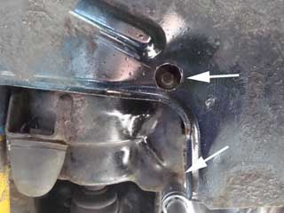 and
those on the right (arrowed - the upper through the hole I drilled in the
inner wing, the other, lower one, already has a socket on it): and
those on the right (arrowed - the upper through the hole I drilled in the
inner wing, the other, lower one, already has a socket on it): |
|
| 5. |
Next you may wish to remove the knuckle pin from the upper suspension arm. I am not 100% sure whether this is necessary. On my car, with its shortened knuckle pin, you can manoeuvre the hydragas sphere without taking it out – and in fact, I’d advise you to leave it in situ if possible, as I managed to break the plastic lower bearing of the knuckle pin when I attempted this first time round (another story!) Getting the sphere out is black magic. I’ve done this twice now, and I
still not clear on how I did it, but essentially what you need to do is to
get the upper part of the Hydragas sphere out of the subframe. The nitrogen
containing part of the Hydragas unit has a flange which tends to catch on
the top of the retaining bracket. I found that by rocking and rotating the
sphere, it just pops out – then simply withdraw. Now you’re committed!!!
You’ve got a car with no suspension at one corner! (picture, right)
|
| 6. |
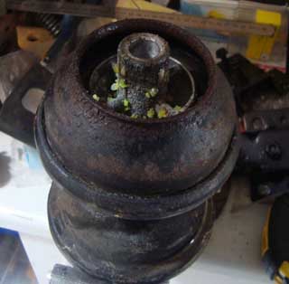 You’ll find that quite a lot of fluid is still sloshing around in the
sphere you’ve just removed. I decanted this into the replacement sphere. I
also removed the lower dust seal from the old hydragas unit – and as you can
see, there’s plenty of crystalised hydragas fluid there, confirming the slow
leak – and why I hadn’t seen it on initial inspections. You’ll find that quite a lot of fluid is still sloshing around in the
sphere you’ve just removed. I decanted this into the replacement sphere. I
also removed the lower dust seal from the old hydragas unit – and as you can
see, there’s plenty of crystalised hydragas fluid there, confirming the slow
leak – and why I hadn’t seen it on initial inspections. |
| 7. |
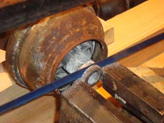 Now we need to get the new hydragas sphere in place. If you’ve got a
Tech-speed lowered car, you’ll need to modify the displacer cone. I found
that they cut off 9mm from the displacer – and you’ll need to repeat this on
your replacement (careful measurement of the one you’ve taken off the car,
and of the one you’re going to replace it with is essential – and remember,
it is easier to remove material than it is to add it). As it is made of
alloy, it’s a doddle. Hacksaw. Just be careful to avoid alloy swarf getting
into the sphere – you can be sure that the rubber diaphragm will not enjoy
having metal swarf being massaged into it by the operation of the displacer
during suspension movement!!! Now we need to get the new hydragas sphere in place. If you’ve got a
Tech-speed lowered car, you’ll need to modify the displacer cone. I found
that they cut off 9mm from the displacer – and you’ll need to repeat this on
your replacement (careful measurement of the one you’ve taken off the car,
and of the one you’re going to replace it with is essential – and remember,
it is easier to remove material than it is to add it). As it is made of
alloy, it’s a doddle. Hacksaw. Just be careful to avoid alloy swarf getting
into the sphere – you can be sure that the rubber diaphragm will not enjoy
having metal swarf being massaged into it by the operation of the displacer
during suspension movement!!! |
| 8. |
Insert the damper spring inside the displacer, and slide the knuckle pin into the displacer rod, and push everything back into their final positions. Key to labels on picture opposite: a - hydragas sphere (painted black), b - displacer cone just emerging from base of hydragas sphere, you can also see the damper spring, c - knuckle pin, and here you can just about make out the trim-height spacer, and finally d - the knuckle sits in the upper suspension arm. |
| 9. |
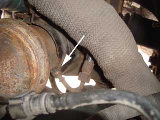
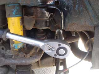
From inside the engine bay, align the sphere so that the unions align – but don’t fasten just yet – we want to re-charge the hydragas line and fill the hydragas sphere as best we can. So pump a few strokes of your hydragas pump (on pressure setting) so that fluid is freely flowing. Once satisfied that you’ve got as much fluid in the sphere as is possible, fasten the union (pictured right). |
| 10. |
Replace road wheels, and drop car back down onto the floor. I then replaced the air filter etc in the engine bay. |
| 11. |
Moment of truth: time to pump up the suspension. I pumped it up to 400psi – which equated to 340mm trim height at the front wheel on my Tech-speed lowered car, but should be around 368mm on a standard car. No leaks, so then proceeded to put back everything else I removed. Set lower damper bolt torque to 44Nm/ 33lb.ft Test drive time, easy to find some poorly surfaced roads round where I live at the moment – plenty of minor pot holes from the winter’s snow! Return and inspect – the car will have effectively settled to its final trim height by now – and should be equal from side to side. Job done! I also found that the ride quality was significantly better – again perhaps indicating that the rear hydragas sphere had been on its way out for a while… |
 Remove the engine inspection cover (as detailed
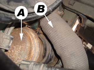 Before attempting to remove the hydragas sphere bracket
(the hydragas sphere is labelled "A" in picture opposite), undo the
hydragas union (17mm spanner). If working on the left rear, then remove the
inlet ducting of the standard air intake (labelled "B" in picture, right) to improve access to the union
allow more ‘swing’ for your spanner.
Before attempting to remove the hydragas sphere bracket
(the hydragas sphere is labelled "A" in picture opposite), undo the
hydragas union (17mm spanner). If working on the left rear, then remove the
inlet ducting of the standard air intake (labelled "B" in picture, right) to improve access to the union
allow more ‘swing’ for your spanner.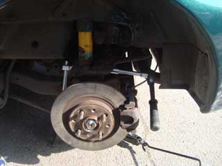
 The lower two bolts are much more accessible. Easy socket access to the
lower right (far right picture), and the lower left (near right picture) once the damper is nudged out of the way.
Once loosened, a 10mm ratchet spanner will finish the job off.
The lower two bolts are much more accessible. Easy socket access to the
lower right (far right picture), and the lower left (near right picture) once the damper is nudged out of the way.
Once loosened, a 10mm ratchet spanner will finish the job off.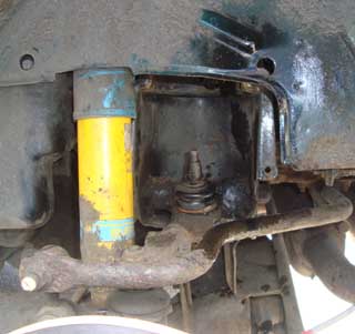 Release and mobilise the hydragas sphere. Rotate it so the base comes
towards you, and you can release the knuckle pin from the displacer damper
in the lower displacer sphere. Put the spring to one side.
Release and mobilise the hydragas sphere. Rotate it so the base comes
towards you, and you can release the knuckle pin from the displacer damper
in the lower displacer sphere. Put the spring to one side.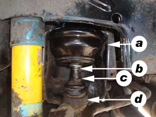 Getting the new hydragas sphere in is even more like black magic than
removal. If you’ve painted up your replacement cone (and if second hand, be
sure that you’ve flushed it with clean water before hand – you’ll be shocked
as to how much ferrous oxide will come out), you can be sure that not all
the paint will survive its insertion! Again, patience, persuasion, rotation
and rocking will get it back into its intended place.
Getting the new hydragas sphere in is even more like black magic than
removal. If you’ve painted up your replacement cone (and if second hand, be
sure that you’ve flushed it with clean water before hand – you’ll be shocked
as to how much ferrous oxide will come out), you can be sure that not all
the paint will survive its insertion! Again, patience, persuasion, rotation
and rocking will get it back into its intended place.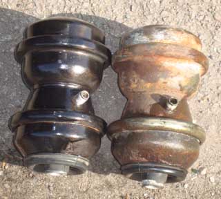 This is a very long set of instructions, but fear not. Although the job is
on occasion rather taxing (getting hydragas sphere in and out!), it is pretty
straight forward. It’s one of those jobs that will save you a mint in garage
bills – and very rewarding. It’ll also de-mystify working on Hydragas! In many
ways, it is easier and safer to work on than conventional sprung suspension
systems (no stored kinetic energy in compressed springs to contend with for
example).
This is a very long set of instructions, but fear not. Although the job is
on occasion rather taxing (getting hydragas sphere in and out!), it is pretty
straight forward. It’s one of those jobs that will save you a mint in garage
bills – and very rewarding. It’ll also de-mystify working on Hydragas! In many
ways, it is easier and safer to work on than conventional sprung suspension
systems (no stored kinetic energy in compressed springs to contend with for
example).