|
This page contains: Introduction | Parts you'll require | How to | Links |
|
|
How to fit a Starter
Button!
|
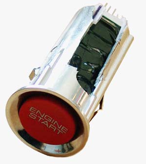
Starter buttons. They've become one of the most desirable 'must have' options to have on sports cars these days - a revolution brought upon us by the humble Honda S2000, but now employed by almost all car manufacturers wanting to give their product a little more 'flash' - which include some far more exotic manufacturers, including Aston Martin!
It hasn't been missed by many that fitting a separate starter button is a surprisingly retrograde step; manufacturers worked tirelessly to find a solution that would bring together security and practicality and brought us the combination ignition switch/ steering column lock that started to be seen in cars in the late 60s/ early 70s. And after all that effort, now we are charging down the route of undoing all that hard work...
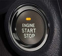 Even Lexus have been bringing out new models with starter buttons - like the rather nice one shown above. |
But this rather misses the point. A bright red starter button is so wonderful to look at. Plus there's the pleasure and drama of the car starting on pressing that illuminated button... what could be better? It's certainly a change from the now mundane key twist...
Can we fit a starter button to an MG - a car that was never designed to use a starter button in the first place? The answer is yes - there are a good number of switches to choose from, and there are even some supposed 'ready to go' kits available from eBay traders.
One of the problems with the starter button idea is exactly where to put the button. A couple of options present themselves - one can either make a hole specifically for the purpose, or one can use a ready made orifice - the one that is currently used by your cigar lighter! This has certainly proven to be an exceptionally popular option amongst MGF owners - and the location appears almost tailor made for the purpose. And bearing in mind that the cigar lighter can be relocated elsewhere in the cabin for powering mobile phones and satellite navigation equipment, this is an option with very few draw backs.
Disclaimer: Please note that while the authors have made every effort to ensure that the information contained in this article is correct and accurate, the authors do not accept responsibility for any damage or fault that ensues from attempting to fit a starter button to your car. Please proceed with caution.
Parts you'll require
So how do you do it?
| 1. | The first step is to remove the cigar lighter from the centre console - this process is covered in more detail here. | |||||||||||||||
| 2. |
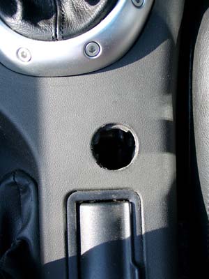 The next step is
to enlarge the hole; the Honda S2000 starter button is approximately 28mm
in diameter, whereas you'll find that the standard cigar lighter is around
21mm - i.e. less than the starter button's diameter. A round file can be used to carefully
enlarge the existing hole circumferentially (it may be of help to make a
template hole in a piece of cardboard first to guide in this process). The next step is
to enlarge the hole; the Honda S2000 starter button is approximately 28mm
in diameter, whereas you'll find that the standard cigar lighter is around
21mm - i.e. less than the starter button's diameter. A round file can be used to carefully
enlarge the existing hole circumferentially (it may be of help to make a
template hole in a piece of cardboard first to guide in this process).The final step in this stage is to use that round file to bevel the trim to suit the S2000 starter switch collar, such that the switch fits flush to the trim when seated - although because the lighter is recessed in the MGF centre console, this step shouldn't be strictly necessary. The end result of your handy work to this point will look something like that shown opposite, right. However, the preparatory work has not quite finished yet as we'll see in step 3... |
|||||||||||||||
| 3. |
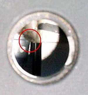 The other
problem: the S2000 starter switch is surprisingly long (90mm) - and can foul some
metal structure hidden under the centre console trim - as was the problem on this late model
MGF/TF - it is just visible in
the picture opposite (highlighted by the red circle). What this means is
that the switch itself needs a little fettling in order to get it to fit
into the available space (but fear not, it will!). The other
problem: the S2000 starter switch is surprisingly long (90mm) - and can foul some
metal structure hidden under the centre console trim - as was the problem on this late model
MGF/TF - it is just visible in
the picture opposite (highlighted by the red circle). What this means is
that the switch itself needs a little fettling in order to get it to fit
into the available space (but fear not, it will!).Before cutting your switch, check that yours fits - I have read other reports where the S2000 fits in snuggly without modification - you could be one of the lucky ones! :o) |
|||||||||||||||
| 4. |
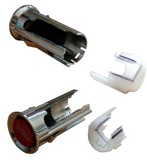 Fortunately,
if modification is a necessity, the
switch is reasonably easy to prise apart into its components - which then
can be modified along its top edge (the area above the 'ENGINE' script on
the button) - as shown opposite. Fortunately,
if modification is a necessity, the
switch is reasonably easy to prise apart into its components - which then
can be modified along its top edge (the area above the 'ENGINE' script on
the button) - as shown opposite.The same switch is shown twice in the figure opposite, but from two separate directions, showing the extent to which the plastic outer casing needs to be 'relieved' by; a surprising amount it would appear! You can undertake this using a variety of methods - perhaps using a 'Dremel' style tool is the easiest way to get a neat and quick result, but a junior hacksaw will likely suffice. |
|||||||||||||||
| 5. |
 Reassemble
the switch - and we're at a point where we can now proceed to the next
stages of this modification. Reassemble
the switch - and we're at a point where we can now proceed to the next
stages of this modification. |
|||||||||||||||
| 6. |
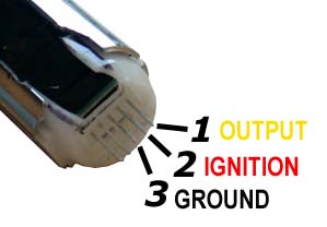 The next step is to
identify the pins on the rear of the button. There is a total of five
pins,
but this modification uses only these of these. The next step is to
identify the pins on the rear of the button. There is a total of five
pins,
but this modification uses only these of these.There is a 'keyway' on the right side of the switch (as you look at the button, with the 'ENGINE START' script orientated in the correct way). On the rear of the switch, the pins are numbered 1 to 5, with pin 1 furthest from the keyway (behind the first letter of 'ENGINE' when comparing at the front of the switch). As an aside, although we're talking about pins 1 to 5, the switch PCB is actually labelled G, H, I, J and K - and even more curiously, the last two pins are completely unused on the PCB - there presence is something of a mystery then... (see workings of the S2000 button here). Pin 1 (yellow wire if you're using the Tarmaceater kit), is the output to the relay. Pin 2 (red wire) needs to spliced into a 12V ignition source. Pin 3 is the ground, and a wire should be sent to ground (perhaps utilising the cigar lighter ground wire - but anywhere on the chassis of the car with good electrical contact will be fine). |
|||||||||||||||
| 7. | Before proceeding
any further, make a record of any stereo codes etc and disconnect the
battery.
Also avoid displacement or damage of any of the SRS airbag system (yellow wires!), although this should not be a problem in the areas that you'll be working in. |
|||||||||||||||
| 8. |
 There are two
ways of wiring up the Honda switch to crank the engine - a simple way (as
espoused by various eBay sellers, including the reasonable value 'Tarmaceater'
kit),
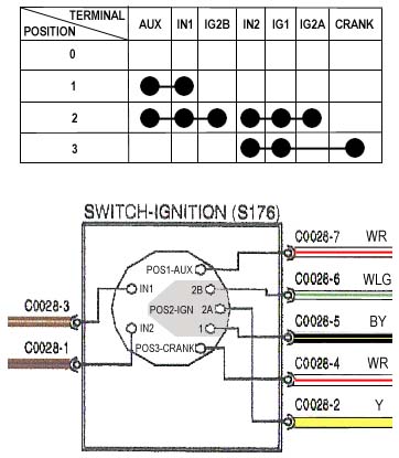
and the rather more comprehensive way. Before explaining the difference, it
is worth looking at the MGF wiring diagram that is shown opposite. Apologies
for the frightening appearance, but it is worth the time understanding its
meaning. There are two
ways of wiring up the Honda switch to crank the engine - a simple way (as
espoused by various eBay sellers, including the reasonable value 'Tarmaceater'
kit),
and the rather more comprehensive way. Before explaining the difference, it
is worth looking at the MGF wiring diagram that is shown opposite. Apologies
for the frightening appearance, but it is worth the time understanding its
meaning.The figure is in two halves. The top table shows how the ignition switch connections link together as you rotate the key from position 0 (off), through to position 3 (crank). IN1 and IN2 are the input power cables straight from the battery via the under-bonnet fuse box - and are both rated at 40A. Connecting these to the other output pins will cause these to go 'live'. The crucial information here is the difference between position 2 and 3; compared to position 2, position 3 effectively switches off all auxiliary circuits, everything connected to IG2B and everything to IG2A - which basically means most ancillaries such as radio, wipers, lights etc etc - in other words anything that is likely to attenuate current flow to the starter motor when its most needed is switched off. The only circuit unaffected by switching from position 2 to 3 is output IG1 (black/yellow). Therefore, if we were to design a push-button starter system, we'd have a circuit that would leave just the crank and IG1 signal live. Figure above compiled using information originally published on the MG BBS by Martin Smyth - see thread archive. |
|||||||||||||||
| 9. |
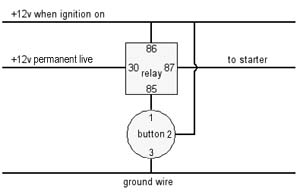 However, the
simple starter circuits do not strive to achieve this goal - possibly in
order to be as universal to as many cars as possible. Instead, they
rely on the ignition key being turned to position 2 (thus taking a switched
live signal), and then without inhibiting AUX or IG2A/B, the switch sends a
cranking signal to the MEMS relay pack via the white/red crank signal cable. However, the
simple starter circuits do not strive to achieve this goal - possibly in
order to be as universal to as many cars as possible. Instead, they
rely on the ignition key being turned to position 2 (thus taking a switched
live signal), and then without inhibiting AUX or IG2A/B, the switch sends a
cranking signal to the MEMS relay pack via the white/red crank signal cable.The disadvantage to this approach is clear; if battery condition is less than perfect on a cold winter's day, then there is a very good chance that current drain from other devices in the car will prevent the engine from starting - or even prevent the starter from even cranking the engine at all! The advantage of this circuit design however is also clear to see: it is simple and cheap! How does it work? Fairly straightforward as you might expect. The relay shown is a fairly ubiquitous 30A Hella (66134), Bosch (SR-2), Siemens type, normally open, single pole, single throw relay. Pins 85 and 86 power the relay's coil - thus, when the starter button is depressed, the switched ignition power goes to ground, through the switch, and energises the coil, closing the relay, and energising the starter cable at position 87 from a permanent live power source connected at position 30. Release the button, and the relay's switch opens again, and the cranking stops. Many have used this type of circuit in their MGs - usually with much success (and there haven't been too many reports of unreliability either), but this circuit could be easily modified to achieve our desired goal. Although the crank signal is only a 10A carrier signal to the MEMS relay pack in the engine bay, it would be 'nice' to use 40A relays given that both IN1 and IN2 to the ignition switch are protected by 40A fuses. Therefore, it may be expected to discover that currents through this circuit could be greater than 30A of the relay typically specified for this type of modification. To achieve our desired aim of only having IG1 and the CRANK signal when pressing the starter button, we could use three 40A single pole, change over (SPCO) relays in parallel, energised by the starter button.
The relay on the left is performing the same function as the relay in the diagram above - switching a live +12V power to the starter circuit when the button is depressed. The wire colours would be Brown/Purple for the +12V (IN2), and the starter signal is white/red (make sure to pick up the correct wire though, as you'll already have noticed, there's more than one white/red wire connected to the ignition switch!!!). The middle and right side relay connects the output to pin 87a thus performing the 'normally closed' function. When the starter button is depressed, the contacts are pulled away from 87a towards 87 - thus closing off these relays. The Middle relay is switching off the black/white wire that is the +12V IN1 input - cut the wire to the ignition switch and connect it to position 30. Connect the other end to 87a and presto! AUX and IG2A will be disabled when the starter button is depressed. Similarly with the righted sided relay: the yellow wire from the ignition switch is cut and connected to position 30, and the other end that goes to the fuse box, connect to position 87a. |
|||||||||||||||
| 10. |
To the practicalities then! If you are using a 'Tarmaceater' ready-assembled kit of parts, the table opposite may be of some help - as this is what Richard found when assembling his kit into his MG. |
|||||||||||||||
| 11. |
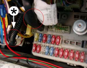 Running
long wires and splicing them into existing cables in the steering column can
be tedious - so it is often easier to pick them up as they enter the fuse
box. Note of course that there are two sets of white/red cables - the one we
want is wrapped up in the loom marked with the asterix in the figure
opposite. Also note that before connector C0028, the wires from the ignition
switch are completely different (Honda colour code I believe - as belies the
origins of some of the steering column hardware!) - look out for the
black/white cable rather than the white/red if looking for the CRANK wire
ahead of this connector. However, if you plan to interrupt IG1 as suggested in step 9, a
longer cable run may be unavoidable. Running
long wires and splicing them into existing cables in the steering column can
be tedious - so it is often easier to pick them up as they enter the fuse
box. Note of course that there are two sets of white/red cables - the one we
want is wrapped up in the loom marked with the asterix in the figure
opposite. Also note that before connector C0028, the wires from the ignition
switch are completely different (Honda colour code I believe - as belies the
origins of some of the steering column hardware!) - look out for the
black/white cable rather than the white/red if looking for the CRANK wire
ahead of this connector. However, if you plan to interrupt IG1 as suggested in step 9, a
longer cable run may be unavoidable. |
|||||||||||||||
| 12. |
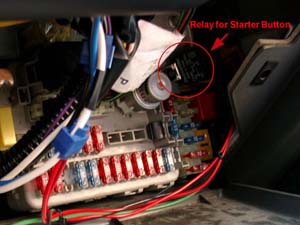 Some
cunning thinking is required to site the relay(s), as space is tight inside
the fuse box. It may be possible to build a new mounting plane for your
relays, as relay mounting blocks are available from suppliers such as RS -
which also has the benefit of providing more reliable connections. Certainly
worth some thought! Some
cunning thinking is required to site the relay(s), as space is tight inside
the fuse box. It may be possible to build a new mounting plane for your
relays, as relay mounting blocks are available from suppliers such as RS -
which also has the benefit of providing more reliable connections. Certainly
worth some thought! |
|||||||||||||||
| 13. | Time to reassemble some trim having got the wiring completed. Before reconnecting the battery, ensure that the car is sitting in neutral and the handbrake is on - in the unlikely eventuality that you've got the connections mixed up (this is a particular project where it is worth checking and rechecking whether the connections and the wires snipped are the correct ones!) | |||||||||||||||
| 14. |
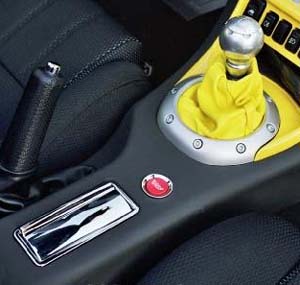 Now switch the
ignition to position 2. The car will no longer start on the key - but thumb
the button and thrumm! Job done! Now switch the
ignition to position 2. The car will no longer start on the key - but thumb
the button and thrumm! Job done!Picture shown is of the installation in Pascal's car. To read more about his installation, click on the link below. In my opinion, it looks stunning! |
Links: Pascal's Starter button | Bodi's starter button instructions for the MGF | Dave Morris' starter button pictures | Broon's starter fitting instructions

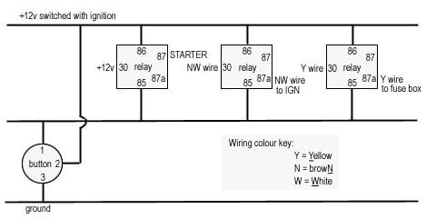 Such
a circuit is shown in the schematic opposite. By using dual throw, also
known as change over (SPCO) relays, we now have the option of having a
circuit that is normally 'open' (or switched off when the relay is unpowered),
or is normally 'closed' (or switched on when the relay is unpowered). These
relays have five pins, with the out put pins numbered 87 and 87a.
Such
a circuit is shown in the schematic opposite. By using dual throw, also
known as change over (SPCO) relays, we now have the option of having a
circuit that is normally 'open' (or switched off when the relay is unpowered),
or is normally 'closed' (or switched on when the relay is unpowered). These
relays have five pins, with the out put pins numbered 87 and 87a.