The project build as
featured in
![]()
![]()
|
|
The project build as
featured in |
Part 7: It is Show Time!
Two weeks and counting...
In my experience, if you don't set yourself a deadline, a
project has a tendency to linger. In fact, there's more than one project of mine
that has barely started, let alone finished over the last few years – including
a supercharged engine rebuild, but that's another story for another day... Do I
have a deadline/target date for Project Shed? Erm, yes... The ambitious target
completion date for Project Shed had been for the MG Live event, 2009, where I'd
dreamt that I'd be lining the Shed up on the starting line for the MGCC Speed
Championship sprint at this flagship event. As television's Jeremy Clarkson
might say: ambitious but rubbish; I am sorry to report that this target was
missed by a tragically big margin!!! In truth, the Shed was really not
significantly further forward than we left off at the end of the last instalment
(Part 6, Project Shed) by the time the “Largest MG Show on Earth” came round.
Which is to say, the engine was fully serviced, but for a fluid change, which is
great, but installed in the wrong subframe (its rust riddled original from the
donor car), which is not. Oh dear. The Shed itself was still standing, bum high
in the air with two front wheels hunkered down on the ground, patiently waiting
for an engine, gearbox and subframe enema...
Yuk, I really don't like the image that that last analogy has conjured up – best
move on swiftly...
![]() The next
target date, which actually was vaguely achievable, was to get the Shed back on
four wheels and transported up to Gaydon for the MGF Register's annual MGFest
event targeted to be held on the 1st and 2nd of August (2009). The car didn't
need to be able to run or stop, but simply be in a state to be pushed around the
site and on and off a trailer. But remember, the engine and transaxle were still
in their original subframe, which was dangerously rotten. And the car had no
brakes. The cams had yet to be timed in the engine, and there was an exhaust
manifold to fit. There was plenty to do, and thanks to work and family
commitments, not to mention a loft conversion in progress on our home, spare
time was notably short. Never underestimate the length of time a job on a car
will take...
The next
target date, which actually was vaguely achievable, was to get the Shed back on
four wheels and transported up to Gaydon for the MGF Register's annual MGFest
event targeted to be held on the 1st and 2nd of August (2009). The car didn't
need to be able to run or stop, but simply be in a state to be pushed around the
site and on and off a trailer. But remember, the engine and transaxle were still
in their original subframe, which was dangerously rotten. And the car had no
brakes. The cams had yet to be timed in the engine, and there was an exhaust
manifold to fit. There was plenty to do, and thanks to work and family
commitments, not to mention a loft conversion in progress on our home, spare
time was notably short. Never underestimate the length of time a job on a car
will take...
By the time that I had some spare time at the same time Tim was also available,
we had no more than a week to get the engine into its new home, and the car
ready to be pushed for its international show début at Gaydon. Time was now
looking very tight. Actually heroically impossibly tight. So over the preceding
week, I started to plan what had to happen. Key to this was going to be to
obtain something capable of lifting the Rover K-series engine and its PG1
gearbox and final drive in one piece. Fortunately, the K-series engine is a
light weight little unit, weighing in at around 100kg with ancillaries and
fluids. The gearbox with fluids is perhaps a little less than this – but
certainly the combination of the two is comfortably under 250kg.
Engine Crane
I am not a weight lifter, there is no way I can lift a weight of 250kg without
help. Tim and I had plenty of discussions about this task, and an engine crane
would be ideal for the job. Tim is a member of the Caterham Seven owners' forum,
Blatchat, and the chaps there had a tool share scheme that we could potentially
make use of. There again, if the engine crane were of sufficient capacity, we
could also use it to lift the car too – and this would make owning an engine
hoist an attractive proposition. And now, of course, with two weeks to go before
MGFest, was not the time to procrastinate. Action! I looked at Machine Mart's
catalogue, and a one-tonne engine hoist (CFC100) cost an eye-watering 160+ quid.
Gulp. How about second hand? There were a few likely looking engine cranes
within 100 miles of my base in North London – so bids were placed. To my
astonishment, these engine cranes – second hand, albeit nearly new – went for
well over 100 quid! And I'd have collect. Yes, there were cheaper cranes
available – but Manchester is a long way to drive to pick up a collection of
battered, rusting bits of steel box section. More reasonable was one of the
stores on our favourite auction site – which was selling new Clark engine
hoists, with guarantee and delivered to my doorstep within 48 hours, for 140
beer tokens. Given the increasingly tight time margins, and time lost on
unsuccessful auctions, this looked increasingly attractive. A bit of keyboard
bashing later, a crane was paid for, and duly delivered in time for the
weekend...
Time to move
As you may recall, I had purchased a 'new' subframe for a ridiculously cheap
price of 5 Great British Pounds some while back, which has now been repainted,
and much of the suspension already transferred across. The ball joints and track
rod ends probably need replacing, along with the metalistic bushes, but these
items could be tackled at a later date, as some worn suspension is unlikely to
make a difference to a car that needed to be pushed around a display area... All
we needed to be able to do is put some wheels on it. Ah. We'd already removed
the brake discs – which were extremely rusty and too worn to be re-used again.
What I hadn't realised was that you can't put wheels straight onto a bare hub –
so in order to make the subframe (and therefore the whole car) mobile again are
some new brake discs. Fortunately, I had already purchased a set of four grooved
240mm diameter standard discs for a little under 150 notes, which is staggering
value for money from our friends on fleabay. I've no idea how durable they're
going to be, but I guess time will tell. And if we're going to replace the brake
discs, might as well replace the brake calipers too. The set I'd sent off to
Tech-speed (01926 632066) for refurbishment had comeback looking as good as new
(thanks guys!) – so new discs and clean calipers later, the subframe was looking
great!
During this time, Tim had spent some time setting the cam timing on our nice
sporty higher lift, longer duration Lotus Sport 135 cams. This really deserves
an article all to itself, but suffice to say, after an hour or so of fiddling,
Tim had the lift of each cam (inlet and exhaust) set to his satisfaction. So he
then readied the still flat-packed engine hoist for use, while I looked at
popping out the drive shafts from the differential.
The drive shafts are held in place by small circular clips that expand into a
grove inside the splined outputs of the differential, preventing the shafts from
accidentally falling out. They tend to be in there 'good and proper' – and it's
no good trying just to yank them out. You need to prise them out, and the ideal
tool would be a wedge-shaped metal fork with two prongs for either side of the
shaft. My Chinese ball joint splitter was almost perfect, particularly with one
of the broken forks pointing off in a jaunty angle such that the wedges acted on
opposite sides of the shaft's splines equally. The shorter left hand drive shaft
came out easily, using that ball joint splitter that I'd 'prepared' (read
'broken') earlier. Then the already loose fork completely let go before I had
opportunity to get going on the longer right hand shaft. Having the right tools
makes all the difference when working on cars – and I don't have the handy
splitter tool that I gather remains available from LandRover. So to work with an
old screw driver. Some scratching of alloy, swear words and general rummaging
about and suddenly the shaft popped out of its housing, more by good luck than
by judgement I suspect, but I am not complaining!
Next, time to undo the engine mounts. The mount at the cam-belt end of the
engine had already been split (where did the bolts go? One was in the boot of
the Shed, not sure where the other one ended up, although I am sure it'll turn
up), which left the gearbox mount and the engine anti-sway bar underneath. Nice
big bolts meant little chance of shearing these bolts off, and with sufficient
leverage, it all came apart easily enough. With a 1 tonne rated nylon sling
wrapped around the engine, we were ready to lift using my beautiful new hoist –
and brilliant, it worked a treat, lifting the engine and gearbox with no
difficulty whatsoever.
The Shed strikes back
I am always suspicious when things are working out well. In my experience it is
invariably a prologue to the main event of big trouble. Not this time, but
rather lots of little troubles...
 Engine mount swapped for a R25/MG ZR item, but the armature to the engine cradle faced the wrong direction. This was substituted for the correct MGF fitment, but then the two retaining bolts were found to be too long! New ones on order, but these bolts were temporarily bodged with our friend the angle grinder to get the engine in in preparation for the rapidly approaching show… |
It proved surprisingly tricky to align the engine mounts to the engine. I suspect that some of this was down to the position we had the subframe relative to the engine, and eventually I did manage to do up the gearbox and engine sway mounts. But not the engine mount under the cam sprockets. Hmm. And the bolts I was using weren't biting well into the threads of the mounts, to the extent that I thought that the threads may have had it; they had been exposed to the elements for a few months – and perhaps the aluminium had corroded. I reckoned a replacement was sensible. This I got from “VVC Steve” (mobile 07766 014 017), which was marked R25. Probably from a ZR we think, but neither of us were sure whether it was any different from the MGF mount. It is and it isn't. The engine part of the mount is the same. The bit that bolts to the alloy mounting on the subframe is not, and moreover requires longer bolts. And since I was hoping to use these bolts, this was a problem. One was cut short, but then we found that the thread wasn't long enough – and these bolts are massive, and certainly larger than any tap I owned... So with the help of our good friend, the power tool fondly named Gordon Grinder, the shoulder on the bolt was ground down, and with the help of a washer, problem solved (Bodge-tastic! Correct bolts now on order from Rimmer Bros).
But getting the drive shafts in was a problem. Perhaps we
needed to lift the engine again, and generally point the 'shafts in the
direction of where they're supposed to go and then drop the engine and gearbox
in, sliding the drive splines in as it went? Er, no. cutting a long story short,
I needed to strip down the brakes and the suspension so that the hub carriers
were free – a bit frustrating, as I'd just spent some while building these bits
up, but there you go: live and learn. With the hubs free, it gave the 'shafts
sufficient movement to enable me to line them up, and pop them into the output
splines of the differential Hurrah! It only took 4 hours to sort that out. Oh
well. Got expert at removing and replacing engine mounts, suspension components
and brakes after that, so there's always a silver lining.
By the end of that Sunday evening, the engine was in its new home, and nearly
ready to be moved into its final resting place – the Shed! But the Shed hadn't
finished fighting back; there were still a few more problems to overcome!
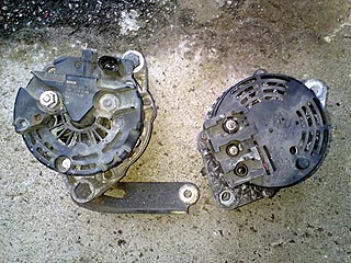 Bosch alternator on the left, Magneti Marelli original on the right. Notet completely different appearance of the alternators and more importantly, differing electrical connectors. I am sure it is possible to wire a later alternator to the earlier wiring loom, but frankly, it should be a lot easier simply to get the correct alternator in the first place! |
First was the alternator. I presume that this was fine when it came out of the donor MG, but by now, exposed to the ravages of nature over a period of ten months had caused it to be seized solid – and indeed, some of the cooling louvers had corroded away almost entirely. It's from a certain well-known Italian manufacturer, so I guess its solubility in British weather should not be entirely unexpected! Steve again came to the rescue with a more modern alternative – this time a nice German Bosch item, but unfortunately the connectors are all wrong. Good grief (or should that be Gotten Himmel?). We shall sort an alternative later, but as this was Wednesday and the chassis needed to be rolling by Saturday, there was no time to sort non-functioning alternators out right now. By way of consolation, I changed over the engine mounts to the solid ones I bought from various sources and should make a real difference to the way the car handles on track when it eventually gets there.
The Night before: get the midnight oil ready for burning!
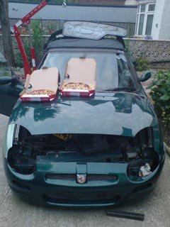 Settling into what was to become a long evening’s work on Project Shed with Andy. What better way to start than with some Pizza? The bonnet makes an excellent picnic table. |
Come Friday evening, time really was running critically short – but thankfully Andy Phillips came to the rescue! He put aside a number of commitments, all in order to make the last big push to get the Shed ready for its anticipated appearance at MGFest. Thanks Andy!
After work, we both set to making the final preparations for the next day – which included shoe-horning in the nice blingy shiny new 4-2-1 exhaust manifold. Unfortunately, this once again required undoing the engine mounts; the replacement 4-2-1 is a rather bulkier affair than the rather poor standard exhaust manifold and downpipe and won't slide easily into the space available between the engine and the subframe's front cross-member.
Undoing the engine sway bar and the gearbox mount (usually more than sufficient in Andy's experience of fitting these manifolds onto engines mounted in the car) was still not enough to get enough clearance to bring the manifold in from below. A scissor jack was able to move the engine away from the subframe cross-member just far enough to bring it through however. But this was not the end of our problems, as we found that the exhaust heat shield mounts fouled the manifold primary pipes. Great.
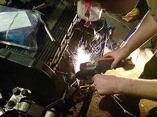 Modifying offside exhaust shield mounting bracket to clear blingy new 4-2-1 exhaust manifold. Pretty fire works! |
Out came Gordon Grinder, and some satisfying shower of sparks later the alternator shield was 'relieved' sufficiently to allow the manifold to fit. Not quite so much luck with the mounting on the opposite side – and with mid-night and dreamland calling, a few choice swear words and deft blows with a hammer saw this mount too clear the manifold. Job done.
Morning of the show
Eight thirty Saturday morning, Andy and I knew we had a job on our hands. The engine and transaxle had been successfully transferred into their new home, the hubs had been reassembled and the assembly back on its wheels. How do we get it under the car now?
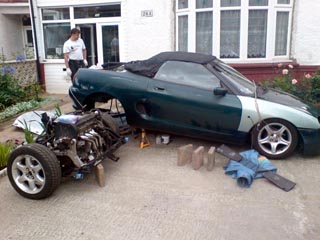 Getting there: Engine is now in the replacement subframe, 4-2-1 manifold is fitted, and hubs rebuilt with new discs and reconditioned callipers ready to go; now all we need to do is get it under the car. Sliding it under from side would work, but without dollies under the wheels, this is not easy. Wheels roll easily in one plane, so… |
Much thought excluded a side entry under the wheel arch. This seemed a good idea, as it appeared that the engine would fit from this direction without having to lift the car quite so high as other approaches, but getting this lot moving sideways was something that took five of us last year on a piece of carpet to achieve.
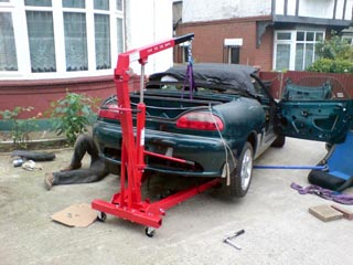
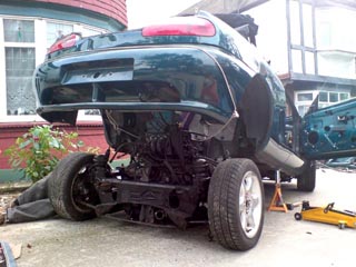 …lift car higher, and wheel in the transaxle assembly from behind! We used the engine crane to get the car up to this crazy angle, and axle stands to support it there. |
There must be an easier way.
There is.
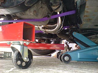
We raised the back of the car still further, using our new friend, the engine hoist, and the car could then be stabilised on axle stands.
We then pushed the transaxle in from the rear of the car, under the bodywork and roughly into position.
Then we lowered the car, so that the rear jacking points were supported on axle stands on their lowest setting.
Next, using the engine hoist again, and the 1 tonne sling under the subframe, the subframe was lifted up into position – a method that allowed surprisingly easy control of the subframe, enabling us to gently rotate the 'fame to permit the subframe mounts to align with their bolt holes in the bodywork...
 The next step was to lift the transaxle assembly with the engine crane up to into the car, and manoeuvre the lump so the mounting holes matched up… |
 …which they did with the aid of an additional jack, and the bolt up the subframe… |
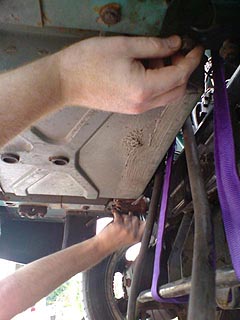 … here Andy and I are performing synchronised bolt tightening – job’s nearly done! |
A number of bolts later and... amazing... Project Shed was on four wheels and possessed of an engine for the first time in two years!!! We lowered the 'Shed down so that it once again rested on four wheels. No hydragas connections yet – so the car is currently hunkered down on its bump stops – but it was starting to look like a car again.
While we lowered the body work onto the car, we had to make sure that the various pipes and cables were not being crushed, and variously ran in vaguely the correct positions. Ideally, we'd rather not drop the engine and subframe again, but obviously if we needed to, we could; we have experience now!
In fact, we're tantalisingly close to being able to start the engine – but now wasn't the time to worry about that. I loosely bolted on the MGF nose cone, put back the plastic boot lid – and Shed was ready to roll.
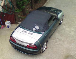 Here it is! Project Shed back on four wheels for the first time in over 2 years, and ready to be transported to MGFest09. Did we make it? |
The Shed proved satisfying easy to push around the in-law's drive, and the steering was notably light – all I hope representative of the amount of weight shed from the 'Shed. And very soon the car was positioned on the drive, ready to be put on a trailer to get up to Gaydon. The only significant problem was the clutch pipe dragging on the ground: this pipe won't be into its final position until we have a chance to drop the front subframe. But the Shed was as ready as it ever was going to be.
MGFest09 - the show
And did the Shed make its big show début?
No.
Despite the sterling efforts by Stew Griffith to find a trailer and tow car (Tim's trailer is only rated at 750kg and therefore inadequate for transporting the Shed that will now weigh somewhere in the region of 950kg based on best guess), and last minute efforts at my end that included knocking on neighbours doors all to no avail, transporting the now rolling chassis of the Shed to Gaydon proved heart-breakingly impossible. A great shame, but the presentation went ahead, so some of you got to hear this latest instalment of 'Project Shed' as near as 'live' as is possible! And next year, I hope that the Shed may make it to what will be the 15th 'birthday' of the MGF under its own steam. Either that or on a trailer purchased specifically for the purpose... we shall see!
Inspirational
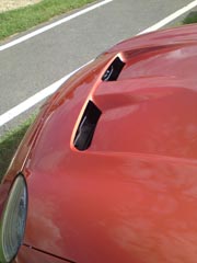
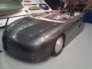
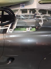
Some more inspiration for Project Shed perhaps? One of the record speed setting MGF prototypes built for the Bonville Salts as an exhibit in the Gaydon Motor Museum – highly aerodynamic, and best of all it’s got…
 |
 |
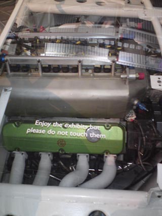 |
... a V8 in it! Well, I can dream can’t I?
![]()
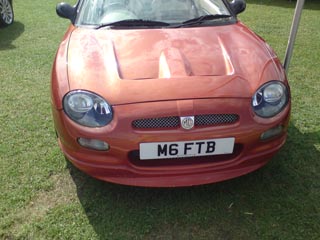
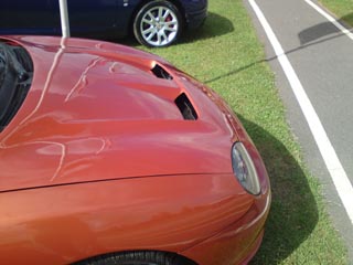
Other inspirations at MGFest 09:
Matt Parker's MGF190:
 |
 |
|
 |
 |
 |