The project build as
featured in
![]()
![]()
|
|
The project build as
featured in |
Part 6: Let's do the Locomotion
Good luck, bad luck
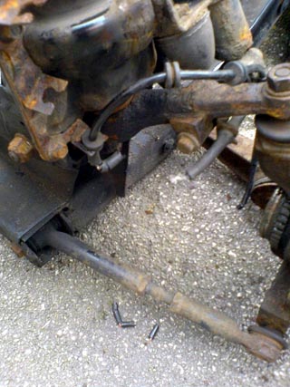 ABS sensor cable in little chewed up bits. Bring back hunting I say! Pesky Foxes... |
With the engine and gearbox removed in situ on the rear subframe, the plan had been to simply service the engine (very easy with the engine out of the car), change vital fluids and pop the whole thing into the Shed with the bare minimum of mechanical disassembly.
 Evil heifer of Misfortune ready to lay cow pats in the path of any well-laid plan. Bar-steward. |
As you will have read in the last instalment, lady luck had gone on sabbatical, allowing the herd of the hated heifers of misfortune to strew steaming cow-pats of disaster all along that planned path to automotive nirvana. Moo! Extensive corrosion had taken hold on the now-departed donor car's subframe. I can't complain about being able to buy a good replacement rear subframe for under a fiver, but I do have to take umbridge over the actions of an urban fox, who must have thought that that the rear ABS sensor cable was a length of liquorish or something equally edible and tempting.
The pest not only chewed through the nearside cable, but also
masticated it into several fragments. Great. Ebay will struggle to come up with
a replacement for that – and anyone who has ever tried will tell you, attempting
to remove an MGF ABS sensor in one piece is not a task that usually ends
happily...
With the ABS sensor retaining bolt threatening to round-off, this task was put
temporarily on the back-burner, to stew in some ProPlus releasing/penetrating
oil. Time then to remove the suspension from the donor car and transfer this
over to the 'new' subframe. This was achieved easily enough – although it took
me about 4hours a side to achieve because, plop, there's another metaphorical
lump of bad-luck bovine manure, it would prove impossible to undo the nut on the
ball joint with out the ball joint rotating. And then my ball-joint splitter
broke. That'll teach me to buy cheap Chinese tools off Ebay. Remind me to do a
list of do's and don'ts of Ebay and car rebuilding at the end of this series!!!
I rather suspect that I'll have stumbled into a good number of the pitfalls
before this project is over...
Scope Shift
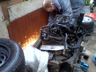 Engine sitting on its subframe, as Tim gets busy with 'Gordon Grinder' releasing seized retaining bolts whilst simultaneously attempting to set fire to neighbour's fence. Engine now ready to be worked on, but we'd over looked something rather vital... how do we lock the engine now that the suspension, brakes and drive shafts have been removed? Err... |
With the suspension now largely transferred to the new subframe (and a growing list of new parts now required to replace sheared bolts or knackered ball-joints), we could move to the engine. Have you ever heard of the phrase “Scope Shift”? Engines offer a lot of opportunity for Scope Shift. And I do mean a lot. Scope Shift is a term that was probably invented specially for engine builders, but was actually coined by the US military (bless 'em).
What's scope shift? It's where you set yourself an objective at the start of a project, but then change your mind about what you're trying to achieve, or decide on some little additions that “won't take all that much extra work to achieve”. In other words, the scope of the project radically alters over a period of time from what you'd originally set out to achieve.
Ha! Well, my
original plan, as you'll have read above was to transfer across a completely
standard K-series engine from the donor to the Shed. Well, now that the engine
needs transferring from one subframe to another before it can find its new home
inside the engine bay of the Shed, and therefore take that much extra time to
do, why not take the opportunity to transfer across some tuning goodies? I
already had a 'spare' 4-2-1 tubular exhaust manifold sitting in the garage
(purchased from the MGF Centre at Silverstone last summer). Plus there was an
opportunity to pick up a relatively light-weight “Trevor Taylor”
straight-through exhaust which may be a story to tell for another day. And then
there's the pair of Lotus Sport cams from an Elise 135 that Tim had in his
garage. And I happened to have a K&N panel filter or two sitting around too...
It would seem rude not to fit all this gear wouldn't it? Especially as the
exhaust on the donor practically fell off the car in a shower of ferrous oxide.
Happily the catalyst remains in good nick, but the down-stream cat studs had to
be ground and drilled out. Clearly the rest needed replacement. The standard
paper air filter needed changing: cue K&N. Nothing wrong with the standard cams,
but why not fit a pair of higher lift cams if you have them? Tim also bought in
a pair of vernier cam pulleys so now we had to fit them! And besides, if you
have to change the cam belt, changing the cams 'isn't that much extra work', is
it?
You see, scope-shift in action!
Locking the crankshaft
Pulling off the cam cover is a doddle. Releasing the cam belt cover was a little trickier, as somewhat inconveniently, one of the retaining bolts is well hidden behind the crankshaft pulley and practically impossible to remove with the pulley still in place. At around this time, Tim and I discovered that we'd made something of a tactical error. Yes another moo-poo of misadventure. We needed to remove the crank pulley – which is straightforward enough if you can lock the crank in position and use a nice long 'breaker bar' extension on your socket. A good metre and a half of leverage is what's needed here; if the crank isn't locked, the engine will simply turn over, and the crank pulley won't be any closer to coming off. A good way of effectively locking the crank in position with the engine and gearbox still bolted together is to leave the transmission in gear, handbrake on, wheels on the ground and crack off the retaining nut. Well, I am sure you've spotted our deliberate mistake: our engine and gearbox, still sitting in their subframe, was devoid of brakes and suspension – so no opportunity here to lock the transmission this way. Of course we could split the transmission, and use the Rover service tool designed to lock the flywheel in position. Of course, if you're doing that, you might was well change the clutch (AP racing clutch perhaps) and consider fitting a lightened flywheel to improve throttle response. Ah ha! You see – so easy to fall into scope-shift isn't it? Perhaps using impact tool would help? The sort that tyre centres use to crack off your car's wheel nuts before chewing up your car's alloys in a ham-fisted attempt to pull off the old rubber. Tim certainly thought that one of these might be ideal to overcome the predicament. And I certainly concur, these airtools are great. Problem is, I don't have either the compressor or the air tool. Electric versions are available – but you need one powerful enough to crack a nut done up to 150Nm torque. They are available, but not especially cheap, and certainly not what you'd want to buy if only purchasing for a single task. Perhaps locking the flywheel is the way forward after all?
Well, a few months passed as winter, work and family commitments intervened. Attempting to get under the car or work on the engine when both as submerged under over two feet of snow is not quite what I would call fun... but the spell away from the car proved most constructive insofar as working out what to do with this conundrum. Clearly, soaking our own imaginative cogs in penetrating oil had managed to tease out some sensible ideas from our neurones...
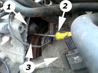 Picture above: that’s how you do it – wedge a screw driver in it! The end of the screw driver is sitting in the ring gear of the fly wheel, just where the starter meshes with it, and the other end is sitting on top of the coil pack. If at first you don’t succeed, bodge it… [1=starter motor, 2=screw driver and 3=left, flywheel ring gear and right, the coil pack that the screw wedges into and against respectively.] |
Tim reckoned that there was a small gap accessible from
under the engine – and there is. Trouble is, it isn't much use for locking the
engine unless there's some really useful locking instrument that I don't have
access to. So the next step was to have a look at removing the starter motor and
seeing whether it is possible to lock the flywheel in place from that direction.
To our surprise (we don't read workshop manuals – they're for girls, and we're
idiots, not girls), in removing the two retaining bolts from the starter motor
housing, a large cover came off the bell housing on the engine side, revealing,
in all it's glory, that marvellous fly wheel! Better still, thanks to the
location of the ignition coil (in the centre of the rear side of the engine
block) on the K-series MPi engine, something to lever against.
Pass the screwdriver! Wedging it in the teeth as the flywheel comes into the
starter motor housing, and the other end under the coil, bingo, the flywheel
locked into position, and finally we could remove the crankshaft pulley. Which
meant we could finally remove the cam belt cover. Which meant we could finally
replace the water pump, the cam belt and the timing belt tensioner. Which also
meant that we could get on and replace the cams for the Lotus 135 Sport items
that Tim had purchased (along with a pair of suitably sexy Piper venier cams).
Forget Rover service tool #### (Okay, it's 18G 1742 if you must
know). Wedge a screw driver in there, and you're
laughing!
This was great stuff – and as you gather, Tim and I could really get to grips
with a number of key jobs on the engine.
Servicing the engine
The water pump was replaced as a 'service item'. The
original showed little evidence of leaking, but I have heard of enough cases of
water pump failure, particularly on 100k+ mile engines that had “just been
through a cam belt service” that had left them untouched. Too many stories in
fact for us to really consider this anything other than an essential service
item. Doddle to replace too and they're not expensive, so if you are in a
similar position I'd recommend you doing the same.
The cam belt was mullered. Well and truely mullered. Teeth had started to come
off the belt – but this may have been related to are earlier attempts to remove
the crank pulley without first satisfactorily locking the flywheel in position.
But again, in a 100k mile engine of unknown history, replacing the belt is
essential.
So is the replacement of the cam belt tensioner. They always look fine until
they run their bearings, and the roller falls off. No cam belt tension means
that the belt can jump over the teeth of the cam pulleys. Which means that the
valve movements are no longer coordinated with the positions of the pistons.
Which means BANG, as valve meets piston in a manner that invariably means
serious bank account surgery...
Changing the cams are perhaps a little bit more of a task and certainly, when
you're dealing with re-setting valve timing using vernier cam wheels, out of the
realms of a standard service regimen. Cracking off the cam ladder – this is an
aluminium casting on the K-series engine, bolted to the top of the cylinder
head, and forms the top half of the camshaft bearings, the cylinder head having
the lower half – is straightforward. Just quite a lot of 8mm bolts to undo. Of
course, our evil uddered ones hadn't deserted us, and of course one of the bolts
started to round off. Being an MG owner, naturally I have an Imperial socket set
in addition to the Metric set that is usually required for work on the F. A 5/16
inch socket tapped on nicely, and off came the last offending bolt. The ladder
will then promptly sprung off the top of the cylinder head under the tension of
the valve springs.
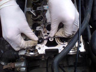 Picture above: using an old hacksaw blade to remove the remnants of the cam ladder sealant before we can replace the cams and put the engine back together again. Use the non-serrated side, obviously… |
Removing the cam ladder will reveal a layer of brown crud
stubbornly stuck to the mating surfaces of the head and cam ladder – this is the
remnant of the sealant that is essential to prevent oil leaks, and of course,
you have to remove the old stuff before replacing with new. A lovely job this.
We used the non-serrated edge of an old hacksaw blade for this task, and it
worked a treat.
Tim had got K-series engine tuning guru, Dave Andrews (www.DVAPower.com), to
supply the replacement goo that I gamely loaded into an old 5ml syringe. But
before reassembly, we needed to salvage the distributor drive spiggot from the
old standard cam and drift it into the 'new' replacement cams.
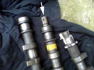 Picture above: three cams are shown above, the two on the left are the up-rated Lotus 135 cams – the one on the left is the exhaust cam, the one on the right is the inlet – with the distributor spigot inserted into the end of it (arrowed). The butchered cam on the right was the original inlet cam that Tim carved up in order to get that aforementioned spigot! You wouldn’t want to meet Tim in a dark alley if he happened to be carrying an angle grinder… |
Tim had clearly developed an appetite for using the angle
grinder, as with a worrying gleeful grin, he set to on the standard inlet
camshaft with an ensuing shower of sparks that looked like the pyrotechnic
version of Victoria Falls (happily, he did make a note of the relative cam lobe
positions before relieving the cam of the treasured spigot). Some wanton
violence later, the spigot was free, and hammered home into its position in the
slightly warmer 135 inlet cam. If anyone is planning a similar task on their
K-series powered car, then if you have a 2001 or later engine running MEMS3 then
all this talk about distributors and spigots can be happily forgotten. Only
MEMS1.9-equipped and earlier engines used the distributor for spark
distribution.
Starting the rebuild
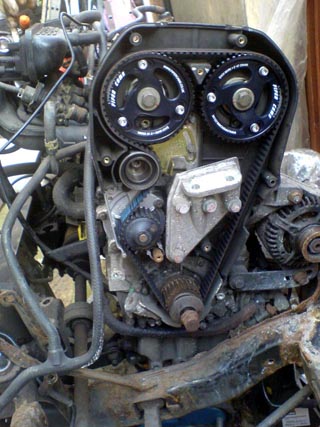 Picture above: new Piper vernier cam wheels looking good in black, new tensioner, water pump and cam belt – just need to formerly time the cams and change the oil, and we’ve practically completed the engine service |
Back to reassembly, it is quickly worth mentioning that it
is NEVER a good idea to use a cam ladder from one engine and attempting to marry
it with a cylinder head from another; the two are honed together to form the cam
bearings, and mixing them from different donors is likely to result in the cams
jamming in position due to millimetric mismatch. Mind you, how often are you
likely to do this, unless buying blind off ebay? As ever, buyer beware!
Back to business, I pre-lubricated the cams and the bearing surfaces with oil
(cam lube is not essential for the K-series I am told, as the top end of the
K-series engine is very well supplied with oil, and moreover we're not using
brand new cams), while Tim busied himself with removing the cam followers
(magnet is the top tip tool for this) and clearing off the congealed black old
oil from their oil journals. Cams in rough position with cylinder 1 at TDC (nice
marker at the back of the crank pulley and markers on the inside of cam belt
cover behind it or this – we'd locked the engine in this position using our
screw driver technique), we were ready to put the cam ladder back on.
Tim applied the sealant goo. Hmm, perhaps a shade too much goo, but the oil channels should all be patent, so no worry about that and I doubt we'll be troubled by oil leaks!!! Then the task of bolting the ladder down. An electric socket driver was ideal for this task and within no time, the ladder was back in its rightful place. Then came the Vernier pulleys (they look lovely – shame to cover them up really, but it is essential we do or else there is a risk of debris causing the belt to jump off at some inopportune moment and lunching the engine), then the cam belt, then the belt tensioner.
Hateful Heifers of Misfortune
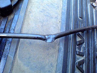 Picture above: great – we squashed the vacuum hose between the head and the cam ladder – D’oh! Replacement is now the only course of action. Don’t do this at home chaps! |
Finally we came to replacing all the covers – and just as
we were looking to replace the cam cover we'd realised that the Enterically
challenged Quadrapeds of Bad Luck had left us with one final surprise. We'd
trapped the vacuum hose (which runs from the inlet manifold to the ECU) under
the cam ladder when we'd bolted it down. Sigh. Everything off! At least we were
now well practised in the art of stripping down and reassembling a K-series
top-end!!! Predictably, the vacuum hose was mullered: a 5mm section was now as
flat as a pancake. Fortunately, a text to my increasingly good friend, Steve,
released a suitable replacement pipe, and all was once again well in the engine
room of Project Shed.
The transformation of Project Shed continues in the next exciting instalment.
And I promise, no more cow references.