The project build as
featured in
![]()
![]()
|
|
The project build as
featured in |
Part 16: MG Live! (2012)
Rain, rain, rain. April Showers? Crumbs – I should have fitted a bilge pump to Project Shed this winter (and spring and summer for that matter as we go through the wettest drought on record). Makes a change from snow I guess. Clearly winter weather without access to a garage means that I don't get much done on the Shed – but fortunately, it wasn't all a doom and gloom wash out – one of the jobs left to do from Part 15 – replacing the upper ball joint on the offside rear suspension has now been accomplished! Hurrah: the Shed is back on its wheels once again.
Ball joints!
You'll recall from the last instalment that I'd given up attempting to remove the ball joint when, despite heaving on a 1.5m breaker bar only the car (and not the ball joint) showed signs of movement. It was on tight alright! I needed air tools! P-O-W-E-R! Fortunately I was able to persuade Tim to bring his compressor and air ratchet with him, and so, one weekend, we set to work.
The stubborn ball joint didn't just pop off, despite the not-so-tender administration of the air impact wrench. In fact the impact wrench had to work so hard the 2hp compressor ran out of air, so we could only really let the impact wrench run for around 90seconds before having to let the compressor replenish the reservoir! But after a while, perseverance paid off, and the ball join started to move, and then it was off. Yay. Screwing in the replacement was a doddle in comparison, and bolting the suspension back together failed to present any further nasty surprises. Which on this project build was something of a surprise in itself!
Cooling diversion
There are, as I am sure you can imagine, a 101 miscellaneous jobs to do on this car – and one was to revisit the coolant pipe work. In a previous edition of Project Shed, I'd mentioned that where I'd removed the coolant hoses for the interior heater from the main coolant system in the engine bay, I'd made "good" by bodging the two stub pipes together – which seemed like a good idea at the time, but collapsed one of the pipes in the process.
If I am honest, I was never really comfortable with that solution. The coolant pipes are likely under undue stress, and these pipes can split, dumping coolant all over the road rather than staying inside the engine where it ought to be. What would be a better solution? I decided to purchase a 180-degree "U" bend black silicone pipe off a certain internet auction site and insert this to re-establish a connection between the now redundant interior heater-feed stub pipes. This is simple enough of course – but trying to undo my previous bodgery was a nightmare! Took me hours trying to separate the pipes: at least I know that this previous solution wouldn't have leaked from the unions! The limited access between the back of the engine and the bulkhead didn't really help my cause, I confess. Still, after some bruises, and the inevitable letting of blood from skinned knuckles (an obligatory sacrifice to the god of automotive DIY - he's a needy deity isn't he? Apologies to DIY deity if he's actually a she...), I was finally able to connect up the pipes, and a cable tie helps keep a reasonably healthy distance between the silicone hose and the exhaust manifold.
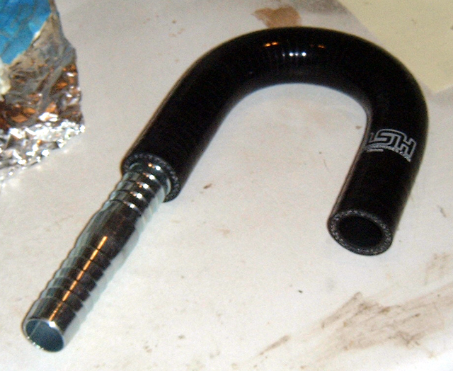 Picture 1 - silicone U-tube – bought off your favourite (and mine!) internet auction site… |
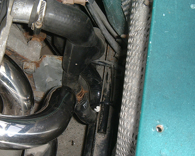 Picture 2 – silicone U-tube in position in cooling circuit, proving a continuous bypass flow, which will, hopefully, help preserve the head gasket in the long term. |
Electrifying (part 2)
So back into the cockpit of the car. Still plenty to do in here, and in particular, the FIA switch needed completing. From previous instalments, you'll know that much of the installation of the FIA switch is complete. I've modified the ignition circuit (I've included my back-of-a-scrap-of-paper electrical diagram for you to have a giggle at), and the remote-pull cable is installed. The switch is mounted on its own mounting bracket ahead of the gearlever, and I've modified it to take the heated screen and rear fog switches. You may also have spotted from the pictures in PS15 that the mild steel was starting to get some surface rust – it needed to be painted. At the same time, I noticed that the plug for the heated window circuit was uncomfortably close to the gear lever bracket – so ideally the mounting bracket wanted moving up a couple of millimetres.
So first things first. I bought myself a small rectangular off cut of 3mm thick transparent Perspex which coincidentally was almost exactly the right size I needed. I wasn't too bothered about its colour to be honest: you won't be able to see it once the mounting plate is screwed back on top; its sole purpose is as a spacer. Straightforwardly, I drilled the necessary mounting holes, made the cut-outs for the switches (see photo) and Bob's your mother's brother: one spacer! Next I splashed some Hammerite on the metal mounting plate. This reminded me why I dislike Hammerite in its brush-on form: it's too viscous, and leaves a horrid finish. Normally this wouldn't bother me, but this panel is in clear view, so I wanted something rather better than that. Hammerite is also a pain to sand, as it clogs up sandpaper really quickly... sigh. In retrospect, I should have mixed the Hammerite with some thinner in the first place: a mental note for next time. Once I'd sanded down the worst of the ridges on the paint, I then sprayed it with black Smoothrite. Spray-on Hammerite is typically too thin (there is a happy medium somewhere?), but on a flat surface, its tendency to run doesn't matter that much as it will simply 'pool' on the panel. The end result of this frustrating painting process is not brilliant, but it'll do the job of keeping the rust bug at bay and it's serviceable.
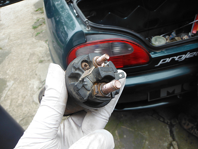
Now this little bit of fabrication was completed, I wanted to compete the wiring to the FIA switch. The back of the switch has two 10mm screw terminals for the main power cables from the battery to the starter, and two 2-pole switches: one open the other closed – which flip flop to being closed and open when the emergency key is pulled. The one that is open when the key is fitted is the alternator grounding circuit; the one that is closed is the ignition circuit. When the key is pulled, the open switch closes, allowing the power spike from the still-spinning alternator to go to ground (through a supplied ceramic 3ohm ballast resistor). The previously closed ignition circuit is then broken, and the ignition power supply is killed – which on my circuit, is akin to removing the ignition key on the standard system. All you need to wire this up are some female spade connectors, a couple of loop connectors to connect to ground, a pair of 25-10 battery terminals (for 25mm2 cable, with a 10mm hole) and some suitable heat shrink!
Wiring the low power circuits is simple enough, and near the gear lever mechanism, there are a couple of M6 threaded bolts helpfully welded into the sides of the "transmission tunnel" which are perfect for grounding. The task of attaching the terminal connectors is made very easy using one of the readily available quality crimps tools. The high power cable from the battery to the starter presents a small problem – it needs to be brought into the car. In fact, a simple solution does present itself on the MGF – particularly following the removal of the heater: the cable can run down the centre transmission tunnel and enter the engine bay where the heater hoses would have run!
Well, this all worked out well, and everything came together pretty easily. Well, one 'minor' problem: the power lead from the FIA switch to the battery was actually a little shorter than I'd like – I may correct that at a later date, but for now it just reaches, and I now had a completed electrical connection once again twixt battery and starter motor.
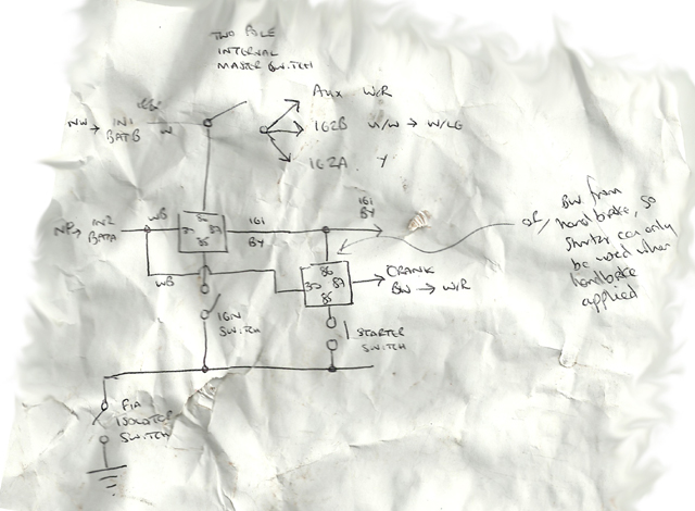 Diagram – the scrap of paper remote starter circuit that does away with the ignition switch completely. Not yet sure whether it works: it’s not been tested yet! |
Picture 3 – Perspex spacer plate – perfect for lifting the switches those vital few millimetres... |
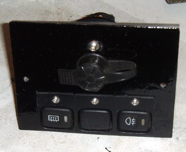 Picture 4 – The completed, and painted, switch panel |
Clutching for success
Those with long memories will recall that I had to fit a new clutch pipe to the Shed, since the one on the car originally had been cut, and in any case, I wanted to use a clutch master cylinder without a clutch damper – so I'd fitted the system complete from the donor car. This led to a diversion down the road of subframe replacement, but that's old news... but what I had not yet done was re-fill the hydraulics! No time like the present is there? I purchased some DOT4 fluid for the purpose, but I had read that bleeding the clutch could be something of a challenge: using a standard bleeding kit tends not to work for some reason, as pumping a dry clutch circuit by pedal was not a sufficient draw for the brake fluid. But I recalled a previous thread on the MGF Register forum regarding bleeding kits, and recalled that there was a vacuum assisted system available. So over to the Bay of E I went, and found a Sealey vacuum brake bleeding kit for not unreasonable money. This requires an airline – and since I was already enamoured by air tools given my experience with the ball joint... well, I'd got myself a compressor for my birthday! I have to say that this vacuum assisted bleeding gadget made this job a doddle. No problem whatsoever! However, I was anxious that the clutch actuator lever would have seized – a not uncommon problem on our cars with the PG1 gearbox – a remedy for which necessitates the removal of the gearbox to replace the aforementioned lever (lubricated ones are available as a replacement from the likes of Mike Satur and Brown and Gammons). However, much to my surprise, pressing the clutch pedal lead to a reassuring movement of the slave cylinder and the actuator lever. Wow! Will wonders never cease? Of course, I have no idea whether the clutch friction surfaces are stuck together until I actually fire up the engine... I guess we'll see....
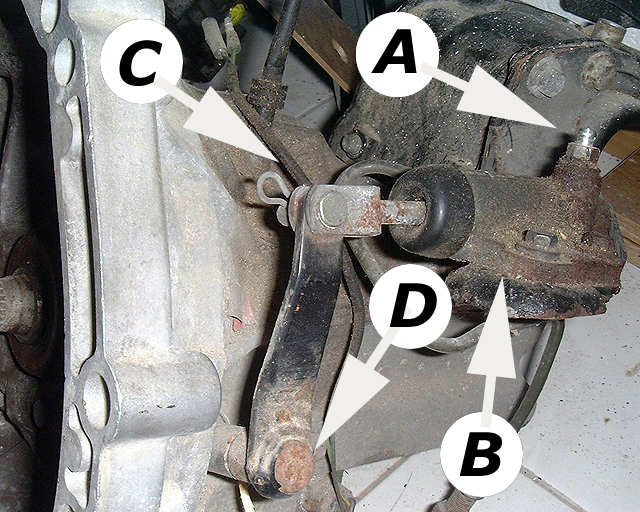
Picture 5 (right) – clutch slave cylinder: A – bleed nipple, B – slave
cylinder, mounted on gearbox housing itself, C – actuator arm to a pivot that
bears upon the clutch release arm, and D – the clutch release arm. These
pictures were taken on a spare gearbox – rather more difficult to picture when
the whole transaxle is in the car!
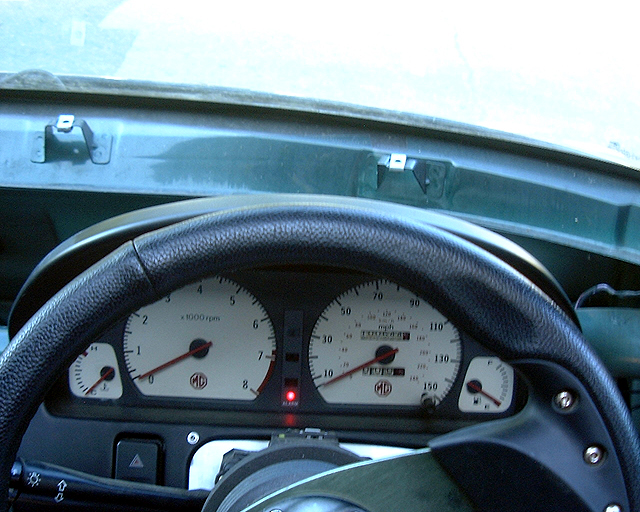
Line of sight
Now I had a seat bolted in position (as featured in PS15) I could find out whether I could see the instruments properly. I'd mounted the clocks directly to the dash support bar which is usually hidden behind the dashboard trim but now is very obvious on this stripped out sprint car. Convenient it may have been, but too high as it turned out – the upper half of the instruments were now obstructed by the upper part of the steering wheel. Aw, nuts. So I needed to think about the solution. The quick answer to this was to make some brackets to mount the instruments lower, and I used the steering column mountings to attach the brackets to the car. The 30 or so mm lower mounting point made the world of difference, and I can now see the vital areas of the dials when strapped into the seat. Inevitably, there is a consequence: the ignition loom that connects my starter circuit to the fuse box is now too short... argh! I need to make an extension! But that was to be a battle for another day – as the car was now edging ever closer to the point where I could go for an engine start. So I have temporarily reconnected a standard ignition switch, which at least I know will work first time – so when the car doesn't start, I know it isn't the remote starter circuit I've made responsible for the problems!
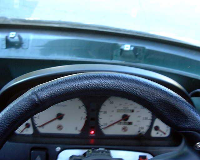 Picture 6 – The top of the instruments were obscured by the steering wheel with the dash pod mounted in the original position on the dashboard cross bar, which was a bit annoying. So.. |
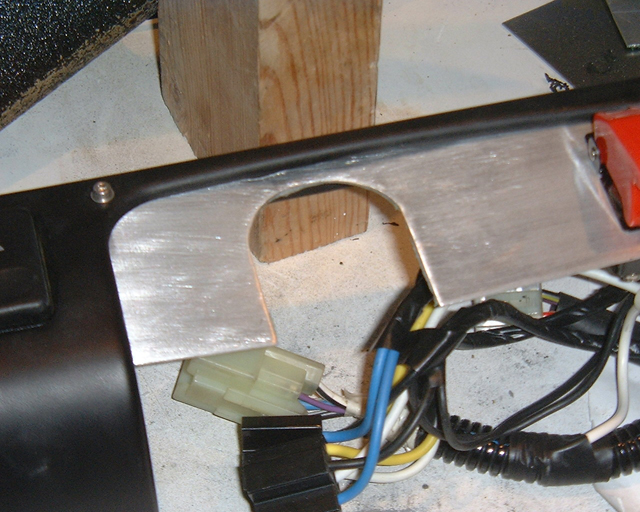 Picture 7 – the dash board had to be mounted lower – a slot was cut in the alloy switch cover, and… |
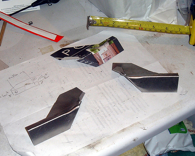 Picture 8 - brackets were made up to mount the dash pod from the steering mounts (first made in card, and the templates then cut out in 1.5mm steel sheet, pictured here before painting. Top left, concept drawing, top right, cardboard template and foreground left and right brackets (before drilling for mounting holes). |
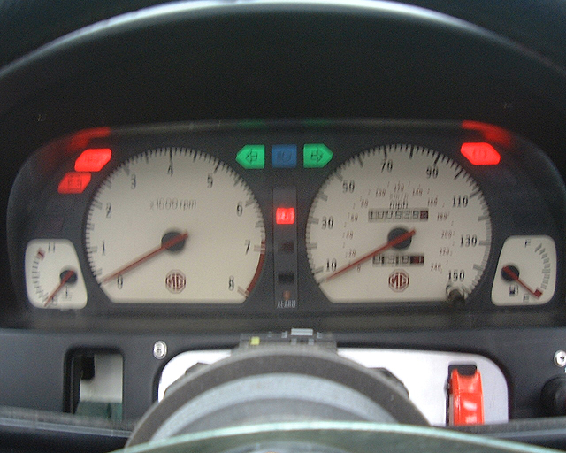
 Picture 9 – the end result – a much clear view of the instruments – and particularly of those important bits at the top of the rev and speed counters. |
Electrifying part 3 – going for power up!
With so much of the electrical system now in place, it seemed that I couldn't put off the next step for long: connecting up the battery to see whether any smoke [see side bar] escaped from the wiring loom. Good news! No smoke! To my delight, dash lights illuminated and extinguished themselves exactly as they should. A bit of clicking from the EPAS relays, but that too worked. Difficult to test the ABS when the car is stationary, but the fault light extinguished itself appropriately. Front lights? Check. The indicators were reluctant to come and play initially, but unplugging and re-plugging after a quick spray of contact cleaner seemed to do the job – and Tim had spotted a blown 20A fuse, and so replaced it with one that he (we?) thought was a spare mounted elsewhere on the fuse box. This did the trick for the indicators – but it did cause a problem that'll come back to a little later... There were quite a few blown bulbs at the back though: fortunately the lamp units salvaged from the spares car yielded enough viable incandescent bulbs to replace the faulty brake, indicator and reverse bulbs.
Similarly positively, when the ignition was switched on, the immobiliser chime came on. I'd already replaced the battery in the key fob – and satisfyingly, the chime was silenced by pressing the "unlock" button. Wow! This was all a bit un-Shed like! Well, seeing that we had "mains" power, I thought I'd check what faults had been logged on the MEMS using my T300 diagnostic reader. Only one fault: a dodgy water temperature signal. For long-term MGF owners, this will come as no surprise: they all do that sir! Certainly, this won't be a deal-breaker come engine start time – a faulty water temperature sensor usually only results in a fast idle as the engine management is tricked into thinking that the engine is still cold. Well, come engine start time, the engine WILL be cold! No problem then.
 Picture 10 – dash lights come on as they should. Wow. Very exciting! |
 Picture 11 – And the head lamps, side lights and indicators work too! Another milestone in the Project Shed build. |
Time for a brake
Before the temptation to start the engine became too great to resist, I felt it important to re-fit the brakes. The BG Development 280mm floating brake rotors had been removed to prevent corrosion through disuse, and I'd also managed to replace the duplicate LH front rotor with the correct RH rotor from BGD themselves (I'd obtained the rotors originally from John Reed, but sadly I've lost contact with him – a great shame). It was also nice to finally re-fit the brake calipers that I'd painted black. Our favourite internet auction site proved a set of extremely affordable Mintex standard-specification front and rear new brake pads. You may wonder why I went for standard pads. Well, part of the reason is that I want to establish a base line as far as possible. The rotors are already significantly larger than the standard 240mm discs, and I'd like to find out exactly how good they are on 'standard' pads before upgrading the pad material in future Shed developments. And I have to confess that part of the reason was also cost: these standard pads cost less than 30 quid per axle set; Mintex 1144 for example now appear to command more than 100 quid per axle set... so for the purposes of bedding in the brakes on an already lighter-than-standard car, standard pads from a reputable supplier should be more than adequate.
I'd already fitted the Goodridge braided hoses, so it was really just a question of bolting things together and then torquing up – all very straightforward. I was a little anxious as to how bleeding the system would go – after all, with ABS, there are longer brake lines and an ABS pump to think about, but with the use of a vacuum bleeding kit, all went remarkably smoothly bar a leaking brake union that was rapidly resolved by nipping it up a little more. Good to find this problem now rather than later!
Now, as you know as well as I, this is Project Shed. Something is bound not to work as planned. Well, yes, you're right. When I came to adjusting the handbrake, I rapidly discovered that I'd run out of adjustment before the handbrake could be effectively applied. Jeepers. Yet another expertly applied custard pie in the face of progress. With MG Live! Rapidly approaching, I resorted to a "hand brick" for parking purposes, and resolved to look at his problem again at a later date. For now, boys and girls, although having working brakes for the first time was a mighty big land mark in the progress of the Project Shed build, there was another, far juicier target to aim for: starting the engine!!!
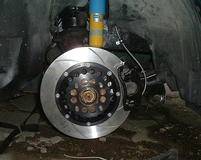
Picture 12 (right) – refitted 280mm floating rotors. They’re gorgeous –
and really declare the sporting intent of Project Shed.
Preparing for ignition!
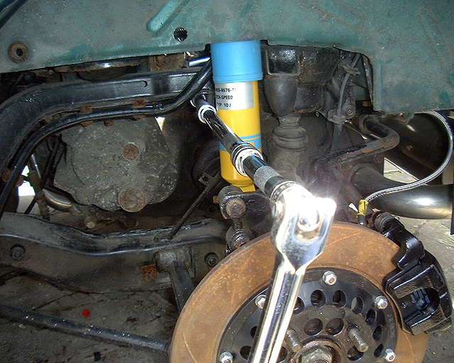
Well, Tim and I had serviced the engine a year ago, put new leads on and we'd changed the oil. But the engine hadn't turned over for years! Had it seized? Before cranking the engine for the first time and risk bent engine bits, I felt it sensible to first ensure that the engine turned over easily by hand. Popping out the spark plugs is easy enough, and then with the offside rear wheel removed, I put a socket on the crankshaft pulley nut, and turned the engine with the ratchet. More good news it seemed: the engine turned over easily enough! Phew... so now we can move to the next stage: turning the engine over on the starter to get some oil circulating before filling with fuel and going for engine start.
A starter for ten...
With no fuel in the system, this was the best time to try turning over the engine. I had already reverted to the standard ignition key – just one less source of potential complication should there be a problem with starting the car. Key in the ignition. Turn to position I. Good – no problem. Position 2 – dash warning lights on: good; immobiliser beeping away enthusiastically. Click of the blipper silenced this. Excellent. All working to plan. Now, crank … nothing. Nuts. Not even so much as a click. It was already late in the day at this point, so further investigation had to wait until the next day when Tim came round to join in the excitement of potentially starting the car for the first time. Unfortunately this day was not going to be "the day". Instead, it was Multimeter time.
The first thing to check was whether there was a voltage between the starter
solenoid to earth. Nothing. Bad contact. Initially I wondered whether this could
it be the FIA switch I'd just fitted in the main power cable to the engine? No -
there was good circuit continuity there. The terminals on the starter solenoid
were however disgustingly corroded: so we cleaned up the terminals, including
the spade connector to the signal input. Wire brush and plenty of elbow grease
appeared to do the trick. We then reassembled everything and tried again.
Ignition key turned to crank the engine: nothing. Perhaps the terminals needed
cleaning on the solenoid housing? This was unbolted (we also removed the piston
- that was a bit of a pain to replace!) and the terminals thoroughly cleaned
until they looked like new. Well, contacts were going to be good now, so we
tried again... nothing. Grrr. Perhaps the earth was inadequate? So the earthing
terminals to the rear bulkhead panel were cleaned and reattached. Still nothing.
At this point we had established that there was power getting to the starter
motor, and that there was a good earth. So the next question was whether or not
the solenoid was receiving the cranking signal. So I placed the multimeter
between solenoid signal cable (the one with the Lucar connector) and earth, and
nothing. No cranking signal. Hmm. Problem with the relay packs behind the ECUs?
Tim cracked open the main relay pack which proved useful as it revealed that the
starter relay wasn't being thrown on cranking. Fuel pump relay was fine however.
So we returned to the fuse board, and inspected the manual for the first time
and discovered that the 20A fuse that Tim had transferred to replace the blown
one was not a spare at all - but the fuse to the starter circuit! New fuse found
and inserted into the empty slot on the fuse board. Starter relay now operated
perfectly, and the signal cable was now showing a healthy 12v. Connected
everything back together and... still nothing.
Arrggghhhh!!!
I think the solenoid/ starter must not have enjoyed their exposure to the
elements. The whole transaxle had spent quite some time under a tarpaulin –
conditions that appear not to have been very friendly for electrical components
– indeed, I already had to replace the alternator due to corrosion (and frost
damage?); perhaps the starter/solenoid had gone the same way?
So off to our favourite auction site once again, for around 20 beer tokens a "new" starter motor was secured and promptly delivered.
I confess, I wasn't particularly looking forward to replacing the starter –
it didn't look that accessible buried down in the engine bay, but in fact it
wasn't too tricky in the end. Actually it was quite straightforward and made all
the easier because I had not replaced the resonator box from the air intake
tract. This leaves a gaping hole in the inner wing of the rear wheel well, but
it also provides brilliant access for a socket and a very long extension to fit
comfortably to undo the two large retaining nuts and bolts. With the starter
replaced, I reconnected the cables to the starter motor.
Was the engine going to crank over now? Tentatively, I turned the key and...
yes! The unmistakable sound of an engine turning over. In fact it turned over
really very quickly; I began to worry that the engine had lost compression!!!
 Picture 13 – Cleaning up the terminals on the starter motor. These were very dirty and oxidised, and won’t have been providing an optimal current. So cleaned up with a wire brush, and now looking much healthier. Except that it didn’t make any difference: the starter still didn’t work. |
 Picture 14 – Removing the old starter motor, using a socket set and a very, very long extension. Did the job a trick though. |
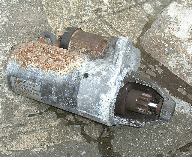 Picture 15 – the old, rather crusty looking starter motor. The strap cable between the solenoid and starter was pretty oxidised, but even connecting it directly to a slave battery, there was no action from the motor. Diagnosis? Both the solenoid and starter motor was dead. It needed replacing. |
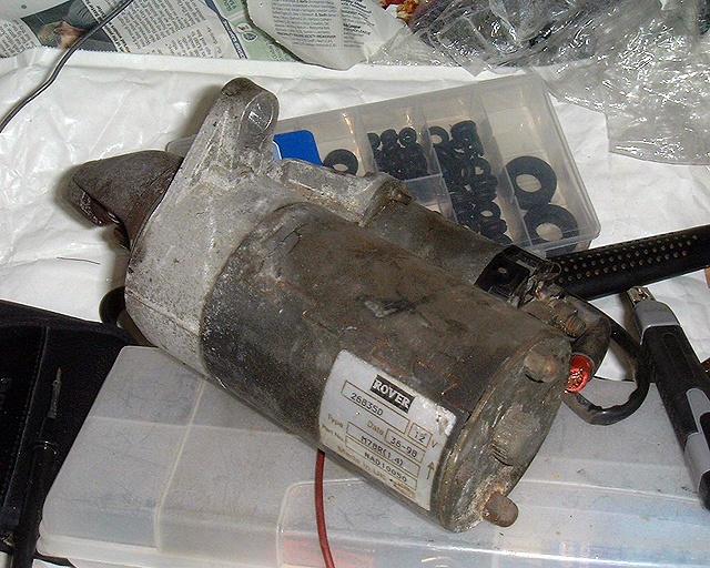 Picture 16 – replacement starter motor from that old favourite internet site. This one looked healthier than the one it replaced, and happily it was healthier than the one it replaced: it worked! |
Final count down... 5...4...3...2...1...
MG Live! was now rapidly approaching, my four year old son and I decided it was time to visit the petrol station. This isn't something that usually anyone would get excited about – particularly given the price of petrol these days, but this was a very special visit to a petrol station! This was a visit to the petrol station for the first tank of fuel for Project Shed! I have a Jerry can with a law-busting 15 litre stowage capacity no less. I put 10 litres of Esso's finest super octane in. I know what you are thinking and I know that the engine won't utilise the extra calorific content of the higher octane petrol (the K-series has no knock sensor), but with all the cleaning additives put in the more expensive fuel, it made some sense to me to treat the Shed with it, to clean all the old fuel residues from the system. By the way, have you tried pouring in 10 litres of fuel into your MG? Takes for ages doesn't it? Thank goodness for fuel pumps on the forecourts.
I'd called Tim to come over to see whether we could get the engine started, but seeing that the battery was connected, and the tank had petrol in it... well, who could resist the temptation?
So I twisted the key and.... the sounds of a humming fuel pump and churning starter motor, but sadly no sign of the engine waking from its slumber. At least, not yet. Close, but no cigar.
If at first you don't succeed... MG Lives!
There next followed a protracted period where Tim and I systematically went through a fault finding protocol. One battery expired, but fortunately I had a spare battery for a diesel engine which had plenty of amp-hours of power stored within it (I'd charged it especially for this purpose the previous night – clever eh?). Checking the first set of plugs, we found them wet and fouled with black goo. So these were replaced with gapped (0.9mm) new ones that I had in stock. Still nothing, so the next task was to check whether we were getting any spark. As it turned out, only intermittently and only weakly. I'd replaced the high tension (HT) leads with vibrant blue replacements when we'd serviced the engine, and upon the demonstration of a good spark from the coil, suspicions centred on these. They were not well made. They have rubber insulating boots that were too long (this could be modified), and the copper connectors too short (which couldn't). Fortunately I'd felt suspicious of them when I fitted them and had kept the original cables safe and to one side. These went back on and... on the seventh attempt, the engine cranked over and wow! The engine started!!! Abso-bloomin-marvelous! Except that the engine cacophony was also accompanied by a shrill high-pitched squeal: the fan belt! We killed the engine just as the alternator belt started to smoke. Hmm. Cranked the engine again, initial shriek and then, brilliant, the alternator un-seized itself, and normal service was resumed!
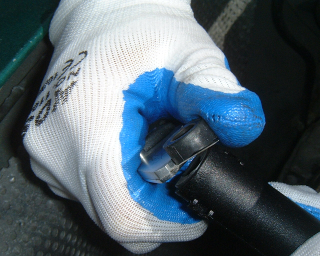 Picture 17 – HT cable woes: the boots on the HT leads were too long, meaning that the leads did not make a good electrical connection with the spark plugs. Simple enough to solve: the rubber boots were trimmed back. Always get a responsible adult to do this bit for you, kids! |
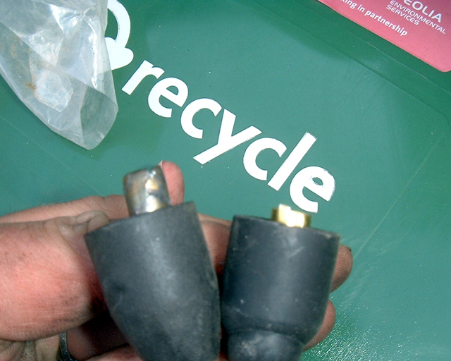 Picture 18 – the original leads, left, had longer contacts than the replacements – another reason why these HT leads were providing an insufficient spark. By this time I was fed up with the new HT leads, and reverted to the originals that fortunately I had not thrown away! |
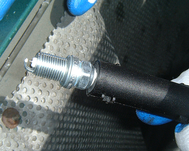 Picture 19 – new replacement spark plugs, gapped at 0.9mm and ready to fit to replace the fouled originals. |
Normal service? That sounds rather mundane. What actually this meant was that, for the very first time, Project Shed had power from a functioning engine. I left the engine to run and to fully warm through. I wanted to know whether the radiator fan would kick in as it should – and I also wanted to know whether the tappets would quieten down. It did and they did. The radiator fan functioned perfectly, and the hydraulic tappets eventually re-charged themselves with oil and fell silent, functioning efficiently and quietly. I couldn't have been happier!
Well, if the engine worked, and was running... well what time would be better than now to check to see whether the gearbox and clutch worked? I couldn't think of any other moment, so slicked the gear lever into reverse eased off the clutch, and the Shed, for the first time, moved under its own power! Only a few centimetres, but significant movement nonetheless!
MG Live!
The last week was something of a rush for me. I needed to get a trailer – and more importantly I need to fit a tow-bar to the MG ZTT! Fortunately the Rover 75 and ZT club forum had enough information for me to undertake the wiring – which was much more complicated than actually fitting the tow bar: frankly the tow bar was a doddle, but figuring out the wiring without diagrams, hidden behind copious amounts of internal trim was a bit a bit of a mare. In fact I was still fault finding when I went to collect the trailer from south London! Got it to work in the end though – although half the trim was still in pieces as I rolled up outside our house to load up the Shed for its trip to Silverstone. And even that trip wasn't entirely event-free: two punctures saw to that. But when I arrived at Silverstone after 8.30pm on Friday, I found that the storm clouds had cleared and I could drive, YES DRIVE Project Shed into the display tent! What an event! Yes, Project Shed is now an international show star! Okay, may be not, but I am pleased to say that there was a healthy interest in the old gal throughout the weekend – and that for me, made all the effort to get the Shed there worthwhile.
 Picture
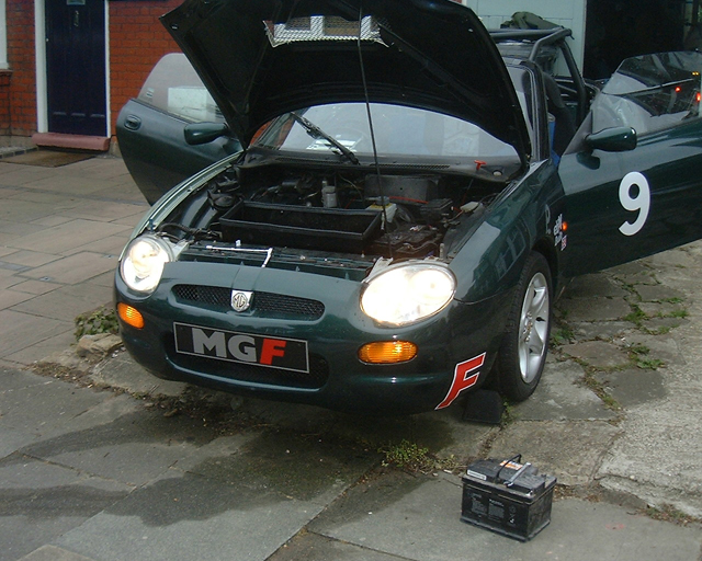
20 – Project Shed on display at Silverstone for MG Live 2012. The car had a
lot of interest for the whole weekend, which was terrific to see. But of course,
Project Shed is much more than just a static exhibit…
Picture
20 – Project Shed on display at Silverstone for MG Live 2012. The car had a
lot of interest for the whole weekend, which was terrific to see. But of course,
Project Shed is much more than just a static exhibit…
Light at the end of the tunnel
This has been a bumper edition of Project Shed, I know, but the Shed is, amazingly, getting ever closer for its track debut. After the Silverstone show had finished, the Shed got its first drive around the track. The perimeter road around the track if you must know – and apart from an intermittently sounding immobiliser alarm bleeper (not sure why this was happening), all seemed remarkably good. The Shed was then loaded onto the trailer, and the next stop? Tech-Speed motor sport near Leamington Spa: Shed had an appointment with a welder – the cage was to be fitted properly, the hole in the wing repaired and the car generally put through a safety check. This was the plan all along: if I am going to take this car out on track, I want to ensure that I hadn't missed anything. Next time, I'll tell you what the chaps at Tech-Speed did, and what horrors they found...
| Smoke and the
electrical system: Electrical Theory by Joseph Lucas Positive ground depends upon proper circuit functioning, the transmission of negative ions by retention of the visible spectral manifestation known as "smoke". Smoke is the thing that makes electrical circuits work; we know this to be true because every time one lets the smoke out of the electrical system, it stops working. This can be verified repeatedly through empirical testing. When, for example, the smoke escapes from an electrical component (i.e., say, a Lucas voltage regulator), it will be observed that the component stops working. The function of the wire harness is to carry the smoke from one device to another; when the wire harness "springs a leak", and lets all the smoke out of the system, nothing works afterwards. Starter motors were frowned upon in British Automobiles for some time, largely because they consume large quantities of smoke, requiring very large wires. It has been noted that Lucas components are possibly more prone to electrical leakage than Bosch or generic Japanese electrics. Experts point out that this is because Lucas is British and all things British leak. British engines leak oil, shock absorbers, hydraulic forks and disk brakes leak fluid, British tyres leak air and the British defence establishment leaks secrets...so, naturally, British electrics leak smoke. [Contributed by John E, Long Beach, CA to http://http://www.sw-em.com/Lucas...RIP.htm] |