The project build as
featured in
![]()
![]()
|
|
The project build as
featured in |
Part 13: Steady as she goes
To-do lists
|
|
Since the last report, it really has been a case of slowly working through the small to-do list required to get the car completed. Did I say small? Sorry, that is a delusion. The list is absolutely gargantuan, not helped by my apparently maschocistic desire to complicate things by embarking on little side projects. You are probably aware of a couple of them already: the little sub-projects include altering the aerodynamics of the car and fitting racey starter buttons on the steering wheel. So it's my own fault really isn't it? The list is so massive that I've often found myself, having taken the cover off the car, just standing there staring, wondering where to start. And once over the initial shock of what's left to do wears off a little, it is a smidge difficult to concentrate on the task at hand: I can start one little job, spot something else that needs to be done, start on that, see something else before I've finished any of the other two things and... well, really not achieving very much progress at all to be honest. So I've decided on a different approach: discipline. Start at the front of the car, and work backwards only as and when I've finished. So this quarter I've fitted the front bumper.
Yes, that's right. I've fitted the bumper. I sense the movement of eyes skywards, and some exasperated utterances along the lines of “when will this car ever be finished?!” I think that my wife often thinks that too. But don't worry; fitting the front bumper actually signals the completion of quite a lot of work at the front end of the car, although the tasks under the bonnet aren't quite complete. Here's what's been happening...
Pull in event of emergency
|
|
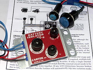
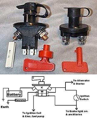
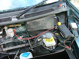
Because Project Shed is going to be largely used in motorsport – sprints, hillclimbs, track days and who knows, one day perhaps even a bit of racing, I felt that it would be a good idea for me to fit an FIA ignition kill switch that, should the worst happen and the Shed fell off the track, the marshalls could kill the electrics from outside the car. There are, as you may have already noticed, two types of ignition kill switch: a cheap one and an expensive one. The expensive one is the FIA-approved one, obviously. But there is a reason for the additional cost; the FIA-approved switch also has two additional switches built into it – one that is open and the other that is closed when the key is installed. Why the additional complexity? You'd think that by simply breaking the connection with the battery would be sufficient to kill the engine and all the associated electrics wouldn't you? Well it would, were it not for the alternator, which is more than capable of providing more than enough power to maintain charge to the ignition circuits to keep the engine running on, although the fuel pumps should stop, ultimately killing the engine. Moreover, by suddenly terminating the battery supply, there can be a large power spike that can damage the alternator's control circuits. The net result of this is that using the simpler switch is not ideal from the safety perspective, and potentially painful on the wallet due to alternator replacement bills. The additional switches on the FIA approved cut-off enables the charging circuit to be grounded through a high-power resistor, which nullifies the alternator charge, effectively killing the engine, and keeping the alternator safe.
|
|
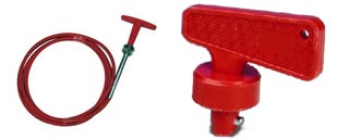
So the extra cost is easily justified, but there is an another point to consider: the size of of the thing. The additional switches on the FIA cut off switch means that it is rather longer than the cheaper version, which can lead to some packaging issues. This is something I realised early on, as I had initially planned to mount it directly on the windscreen scuttle, since the switch is fitted with a rubber cover, and seems to have been designed with outdoor use in mind. However, to fit it here would have meant some major surgery to the bulkhead. This didn't feel right, but I knew that the cut offs were originally fitted on the MGF Cup cars on the nearside scuttle panel. So I phoned a friend for advice: Marvin Humphries of Tech-speed motorsport. Tech-speed motorsport, as many MGF affictionardos will know, developed the original MGF Cup cars, so I was curious as to how they did it when these cars were first built. This turned out to be a hugely useful and enlightening conversation. It turns out that the actual cut off switch was never actually mounted on the scuttle – but rather a remote button switch was mounted on the scuttle trim; the Cup cars using a trick electrical cut off circuit that is still available for fitment to racing cars. Being Motor Sport related electrotrickery, it isn't cheap – over 250 beer tokens, which, let's be honest, is probably 250 more than the car is worth, so not a serious contender as a solution for Project Shed. However, Marvin mentioned that they had just finished a new Cup-spec racer in a 2008 model year MGTF 500LE body shell. They hadn't used an electrical switch on this one, but rather a simple mechanical remote, consisting of a danger-red coloured T-handle and a co-axial cable (rather like bicycle brake cable), that then pulls on and rotates the key of the ignition cut off switch which are actually already made with a small hole for precisely this job. The ignition key is spring loaded in the switch housing, so all you need to do is rotate it, and it will automatically pop out, killing the ignition in the process. Perfect. And the best news? Well, I hadn't thought of the weather being a problem, but keeping the switch inside the car means it stays dry, and hopefully more reliable. Plus it could be in a position for the driver to activate in the cabin in the event of it needing to be used. Neat.
|
|
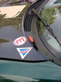
So off to the bay of “E”, and 10 quid later, a remote T-handle and 1.5 metres of coaxial cable were winging their way to me in the post. The T-handle and cable assembly is much smaller than the ignition switch, and as a result, much easier to fit. I had to remove the scuttle trim of course – and seeing that this trim on the Shed was actually in far better condition than the one currently on my road car, I thought I'd take the opportunity to swap the two around. Taking these scuttle trims off can be a pain in the posterior however. The self tapping screws that go into the scuttle to secure it have little plastic covers that need to be levered off. Except I can't figure out a good technique for doing this: they either pop out perfectly easily, or are beastly, hanging on limpet-like for dear life, usually resulting in mangled plastic that is later all too clear to see. The answer I applied was to drill small holes into each of them, and lever them out with a small screw driver. This is destructive, but it preserved the scuttle trims and I was able to swap them over easily enough. New scuttle trim screw covers are disturbingly expensive from X-Part, but I bit the bullet and got new ones to replace the ones I had destroyed.
|
|
|
|
I drilled a suitable hole through the scuttle panel for the T-handle/cable assembly, sprayed on some paint on the exposed metal and mounted the outer cable of the remote pull handle to the scuttle panel. The really tricky part was to drill a hole in the scuttle trim that aligned perfectly with the hole on the scuttle panel. After careful measurement and re-measurement I drilled a pilot hole. And another. And another. Ahem. Oh well. I've added some lightness. This enabled me to run the cable into the car through an existing hole in the bulkhead (it was for the now unused heater matrix bleed nipple), to which I fitted a suitable rubber gromet, and into the cabin for it to run to the FIA switch. I'll tell you about the rest of the fitting in the next instalment, because I need to tell you about a couple of other jobs before I fitted the bumper...
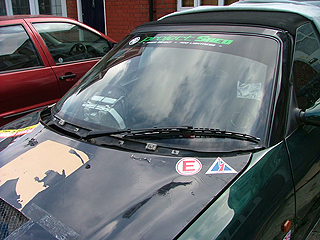
Racy Single Wiper
Since the scuttle trim needs to come off to get to the wiper spindles, and I needed to take it off for the ignition cut off remote handle pull installation, here was a perfect opportunity to fit the Storm Wipers single wiper conversion. I had actually visited Storm Wipers three years ago specifically to get a single wiper conversion manufactured for the MGF as it hitherto hadn't existed, and I got the prototype made for my other MGF, along with the kit for Project Shed. As it turns out, 1990s Rovers are ideal for single wiper conversion, as our friends in Longbridge cunningly engineered their cars to be easily manufactured as either right or left hand drive with little or no difference in body pressings. As a result, one of the wiper spindles is mounted in the dead centre of the car – which is not the case on many European designed cars. The Storm single wiper a very successful conversion too, I've been using the one on N7, my road car now for three years without any problem, and it is beautifully engineered.
|
|
Three years? Staggeringly, yes, it hasn't taken me this long to get around to fitting it to the Shed, oh dear me. But now was the time. It should be mentioned that the single wiper conversion being fitted is a little bit trick: it has the screen washer built into it, so I can remove the standard washers from the GRP bonnet when I get around to repairing it. A single wiper conversion enables me to loose a wiper and its associated mechanics, so a there's a bit of a weight saving there, as well as looking racy.
|
|
The existing wiper arms just lever off their spindles, so that's easy enough. Then, with the scuttle trim removed, you can remove the spindle retaining nuts – which are quite sizeable at 32mm - and you ideally need a deep socket to fit over the top of the spindle. Fortunately, I had one, but if you happen to have a suitable open, ring or adjustable spanner, then that'll do the job nicely too.
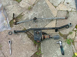
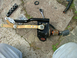
To remove the wiper assembly from the car, you need to run the motor so the wipers are pointing up the screen – easy with the battery attached, but the Shed remains, for the moment at least, electrically inert. So the easiest way round this problem I found was to remove the motor casing. I had wanted to do this anyway, as I was unsure as to its condition – and to my surprise, the motor's internal windings, bushes and connections all looked to be in remarkably good condition. Which was a relief, as I didn't fancy buying a replacement. With the cover removed, it is then possible to rotate the motor by hand, and position the wiper levers in their most compact position. The motor can then be disconnected from the wiring loom and unbolted from the bulkhead, and the whole assembly withdrawn.
|
|
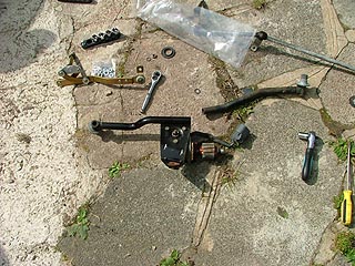
On the ground it was possible to survey this neat wiper assembly. A couple of circlips retain the spindles within the frame of the wiper assembly, and on removing these, and undoing the wiper gearbox cam lever, this can then be withdrawn and discarded (or, if you are like me, put in a box somewhere, because you can never be too sure when it will come in use again in the future). I then came over all brutal and chopped the nearside spindle extension off the assembly before installing the single wiper mechanism. I may come to regret this, as the second spindle mounting stablises the assembly on the scuttle panel, but I've left it as it is for the moment. Before finishing the conversion off, the wiper motor needed to be returned to the 'park' position. The easiest way to do this is to connect it back in the car, turn the ignition on, and let the motor return to park automatically. Erm – except that the Shed is electrically dead remember? No worries: I connected it to N7, my road car. Once the motor's outer casing was replaced, the motor swung back to life. Slightly worryingly, it was a bit noisy – either it's the motor or its the gearbox, I am not sure, but will be something to look at again later. Hopefully some lubrication will quieten it down after some years of disuse resulting in dried bearings.
|
|
So now, with the motor in 'park', I could tighten up the wiper cam and finish the assembly of the single wiper conversion. This is now much smaller than the standard assembly, and as a result, much easier to fit, so no problem.
The washer jet tube simple threaded through the air grille in the scuttle trim, and attached up to the standard washer pump hose. Yet another Project Shed googley here: the pump motor had somehow lost its rubber sealing grommet, so the tank wasn't water tight. Another couple of quid fired off in Rimmer Bros' direction, and the tank now holds water – and is now even filled with washer fluid! Wow!
Air ducting and fitting the bumper
|
|
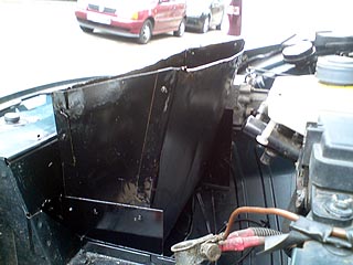
To the final part of this chapter – yes, I cobbled together the final part of the aerodynamic modifications left off in part 11: the ducting to the radiator from the bumper and then through the bonnet! I'd left this part of the project with the radiator fitted, and the immediate ducting behind the bumper in place, but not any of the ducting required to get the air into the radiator nor out of it. Nor had I made a hole in the bonnet yet. Well, no time like the present is there?
I'd
managed to obtain some thin gauge scrap steel with which to fabricate a suitable
duct. Using some cardboard templates, cut four sections of the bonnet duct, pop
riveted them together and into the car. Hmm, sounds easy eh? I then splashed
some black paint over it, and the job's a good 'un. Of course, a bonnet duct is
not much use unless there is a hole in the bonnet for the air to duct through.
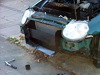
Those with long memories will recall my agonising on the potential options, and
in the end I simply cut a hole using a jigsaw in the bonnet in the area of high
negative pressure that I'd previously mapped on the bonnet. The hole is
admittedly a bit rudimentry, but it seems to do the trick, and with some grille
mesh behind it (some spare MGF lower grille mesh), looks remarkably subtle. It
will certainly do the job for now!
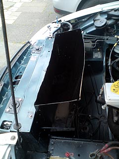 |
 Left and above: he radiator-bonnet duct. Like the bumper-radiator duct, simply fabricated out of sheet metal. Use of cardboard templates made this job deceptively easy. |
 The bumper-radiator duct. Simply fabricated out of sheet metal and pop-riveted together. It doesn’t need to look nice; it’ll be hidden behind the bumper! |
Next up is the bumper to radiator duct. This is to stop air from flowing behind the bumper rather than through the radiator – and to this end, used what left I had of the scrap steel sheet, and cut it into 5 sections – one as the floor of the duct, attached to the car using existing captive bolts in the subframe under the radiator itself, and two on each side of the bumper bar – a thin one on the bumper side, and a thicker one on the radiator side – repeated on each side of the radiator. Again, pop-rivets, a splash of black paint and job done.
It was at this point I realised that there really was nothing else to do but to put the bumper back on. Well, obviously I had been taking the thing on and off every time I had worked on the front of the car, but now I could put back the bumper “permanently”. And fit, for the first time, the front indicators! The new radiator duct made fitting the bumper now a little harder, but it went on well enough (after altering the shape of the duct behind it a little with a bit of gentle thumping), added the screws to the front wings, the screws attaching the bumper to the bonnet landing panel and of course the two bolts in the indicator appetures. And finally, yes, I could fit the indicators. Glorious orange ones! And they look great!
And finally...
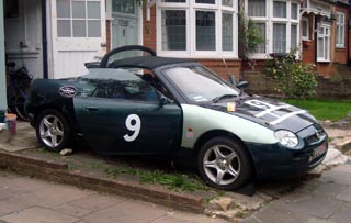
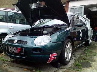
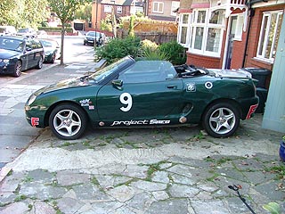
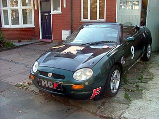
The eagled eyed ones will no doubt have spotted something: Project Shed is now resplendent in Project Shed Racing Logos! This is thanks to the efforts of a local sign-printing company, Aspect Signs. They could even vinyl wrap the whole car, which would save me the effort of re-spraying the car, but that would cost the thick end of two grand – so may be some other day. But with the new appliques, the old Shed is really starting to look the part. It has logos down the sills, over the top of the windscreen, and at each corner of the bumpers, taking inspiration from the original MGF Cup car liveries of the 1990s.
 |
 |
 |
|
Above: the new Project Shed logos – with “F”s at each corner, which is intentionally reminiscent of how the MGF Cup cars looked in the late 1990s. |
Above: I can’t take things too seriously. Ebay find “I survived the Scrappage Scheme” sticker |
|
Oh yes indeed, progress is being made. Slowly perhaps, but
surely.
Post Script
 |
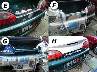 |
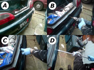
| Predictably, even putting stickers on Project Shed proved to be quite a trial! The rear panel between the rear lights was heavily dented – so there was no way the sticker would have fitted neatly (A). So there was nothing for it: time to repair the rear panel. First, holes were drilled (B), so that the end of the sliding hammer could be screwed into the panel (C). The sliding hammer could then be assembled, and then the dent pulled out (D). The holes – of which we had to make a few – were then painted to prevent rusting (E). Now the much shallower dents could receive a skim of body filler (F). Once flattened with wet and dry 1200 grit paper, the panel could be resprayed (G). And now, at last (!) the sticker could be applied! (H). Don’t worry folks, I am not giving up my day job!!! | |