The project build as
featured in
![]()
![]()
|
|
The project build as
featured in |
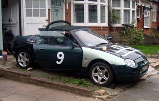
Part 12: Electrifying
Loose ends
|
|
In this quarterly report we have a temporary reprieve on body work modifications that we left the last instalment with – more on this in a later report, but what we have concentrated upon are lots (and I mean loads) of little jobs that hitherto been put off. Not because they're particularly difficult tasks, but because, err, they're dull, boring things to do compared to nailing on engines, subframes wheels, lightweight bonnets and the like. And actually, they're the sort of jobs that make dull copy for quarterly club journals too. But seeing that I haven't actually done any exciting jobs since the last report, well, tough: you're getting the dull stuff this time!
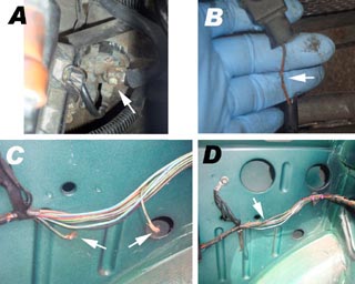
Where does this wire go?
|
|
The engine bay is one of those areas that I'd left a lot of those small little tasks. In the rush to get the Shed on its wheels for MGFest09, the Shed had been dropped on its rear subframe, but scant interest paid in connecting up either the engine harness or the plugs that interface between the engine and main body wiring loom. Well, there's no time like the present now is there. Luckily, the wiring looms are designed to almost fall into place – so despite the fact that it is now a couple of years since I took the looms off the donor car, it is actually reasonably easy to figure out what should be connecting to where. The relay packs behind the ECU were connected up without problem, and the earth cables connected to the bulk head in a similarly trouble-free fashion. Sensors were also reconnected – although the oil pressure warning wire showed some evidence of damage – so this was repaired and wrapped in insulation tape before being connected up. Similarly, one of the wires in the boot had been severed and the insulation exposed at each end. This almost certainly was due to someone retro-fitting a high level brake light at some point in the past. I must be the only person in the world to have ever reversed this modification, as Project Shed is not going to be fitted with a high level brake light; the racing-spec GRP boot lid won't accept one. And it adds weight. Oh, and what's wrong with the normal brake lights anyway? So the wires were soldered together, and insulated with heat shrink. You see? This is all riveting stuff isn't it? I also re-ran the main battery cable from the front bonnet area to the starter motor at the rear, attaching to a post screw on the starter. I'd managed to loose the nut off this post a couple of months ago – causing some annoyance, but amazingly I found this under the nearside tyre when grubbing under the car for something else: hurrah! my luck can change for the better! By now the Shed had a near complete electrical system.
|
|
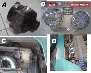
Near complete? No alternator. Those Project Shed fans with very long memories may recall that the donor car's alternator was scrap: it had completely seized, and the outer casing showing evidence of advanced corrosion. Not good. I had obtained a spare – but annoyingly, later cars (with MEMS3 engine management) have a different Bosch alternator to the earlier (MEMS1.9) MGs which had a twin post Magneti Marelli alternator. Well, I'd got another on exchange, and now seemed to be as good a time to fit it as any. I am not sure why I had taken so long to do this to be honest. Pretty easy job – although the new 4-2-1 manifold I had fitted did make access a little harder when it came to sliding out the upper retaining bolt. But a hammer – that stalwart of the DIYer's tool chest – came to the rescue and enabled me to hang the alternator from its upper mount. The lower mount goes into an elongated slot in an adjustable bracket, and the only thing to get right here is to ensure that the adjuster screw goes through the slot at the end of the bracket to enable the alternator belt to be correctly tensioned. Again, straightforward enough, although probably 100 times easier had I done this before slotting the engine and subframe back on the car. Still, no problem. Once again, the cleverly designed harness meant that the cables to the alternator could only be fitted in one way, so job done. Another first: Project Shed now has what is an essentially complete electrical and charging system. To celebrate I changed the ignition HT cables – which look fast in their beautiful blueness.
Modifications and electrotrickery
Being Project Shed, it was unlikely that this car was ever going to end up with completely standard wiring. Simple modifications included deletion of the boot lid wiring loom (wires terminated and the ends wound into the main harness – I may need to come back to this a little later to ensure that the alarm functions correctly, as this is dependent upon the status of the boot lock and catch), and of the under bonnet lamp. But the biggest plan is the removal of the ignition barrel from the steering column.
|
|
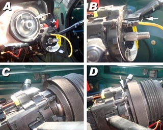
Why do this, I hear you ask. Well, with all the interior trim removed and the solid metal steering lock assembly hanging off the steering column fully exposed, all of a sudden it no longer looks like a convenient starting switch combined with security feature. Instead, it looks like a blunt weapon designed to destroy one's knee cap in the event of an accident. I felt that it had to go. And besides, everyone knows that race cars start on a button, don't they? And where to mount a button? On the steering wheel of course! Very F1.
Ah, the steering wheel. I wanted to change the standard steering wheel for something without an explosive powder puff installed into its boss for something that weighs a little less, has a smaller diameter, and a slightly thinner rim. Naturally, our favourite internet auction site came to the rescue again. A loose copy of a Momo steering wheel design, it even had a centre horn push complete with an MG logo! Brilliant! Had to get one of these – and a couple of mouse clicks later, it was mine. It looks great – and for 30 quid, I can't complain. Obviously, it didn't come with the correct mounting boss – so I had to look elsewhere for one of these, and found what I was looking for at Demon Tweeks. Annoyingly, this cost at least as much as the steering wheel had... grrr... but it promised to enable me to fit the steering wheel directly onto the MGF steering column without any problems.
Well, yes and no. Yes, that's right, Project Shed throws yet another curved ball. The Momo steering boss was designed for Rover 200/25 and ZRs, but is also compatible with MGFs. It even has a cut out for the connector on the rotary coupler to sit into – all, so I thought, was well – particularly when the boss slid smoothly onto the splines of the column. But I hadn't noticed that the boss wasn't sliding all the way down to its register landing on the shaft: the rotary coupler's electrical connector is too tall for the recess in the boss. And that's before connecting up the steering wheel's plug to it. Great. This has stalled this project – and at the moment I am trying to figure out a solution, and I'll let you know how I get on with this one next time.
Given the loss of momentum here, I naturally did what all car enthusiasts do when faced with an apparently insoluble problem: move on and do something else.
Exhausted
|
|
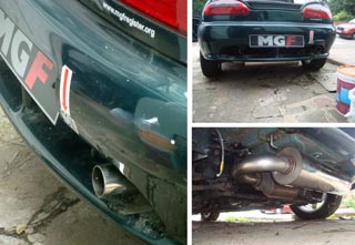
There was a big, shiny exhaust system sitting on a shelf taking up space. Hmm. Plus, I had a catalyst, and a stainless flange for the manifold. It seemed rude to ignore this any longer. I was only missing a couple of gaskets. A couple of quid later, the parts were ordered from Rimmer Bros, and arrived through the post box 24 hours later. Great service. No excuse now.
Some of you may have already recognised the exhaust system – and it is a design that I am making a happy re-acquaintance with: it's a Trevor Taylor system. Old friend, Neil Willetts, developed relationship with Trevor way back in 1997 I think. Neil felt that the standard exhaust was too quiet, and could be made more efficient if it were a straight-through design (the standard system being a baffle plate system). And so started a brilliant collaboration that sadly came to a premature end with Trevor's untimely death in 1999. However, Neil resurrected the design, and in Trevor's memory, his name remains associated with the newer systems, which are now produced in small batch numbers. Mine is a little bit special: it's a motor sport system with one pipe deleted, and is therefore a couple of kilos lighter than the standard exhaust system. Light weight and cool noise – what more could a boy racer wish for?
I've attempted to change an exhaust system once or twice before – and usually have come out the other side regretting ever having started (sheared catalyst mounting studs usually). But this was much easier. There was no old exhaust system to contend with; this had almost literally fallen off the donor car, and was junked a long time ago – so really, it was a question of just bolting things together. And so it proved. And remarkably, everything appears to have aligned up nicely, which is testament to the fabrication of both the exhaust system and the manifold (an MGF Centre item). I can't wait to fire the engine up!
Cool it!
Well, there actually isn't that much more to do before I can consider attempting firing up the engine for the first time. The electrical system is now complete. The fuel system is all there. Now the exhaust is attached (another first on the Project Shed build). But there is a problem with the cooling system. Since deleting the passenger compartment heater matrix, it has meant that the cooling system had two pipes venting to air that hitherto would have been connected to the heater matrix circuit. I had imagined that to complete the coolant circuit would involve some fabrication – perhaps a 'U' bend of some sort. And then I was just looking at the pipes and thought “why not just connect them together?” Well, this is a bodge of astonishing simplicity – and do you know what? The two pipes connected together remarkably easily. Not in an ideal way, by any means – the hose has a kink in it now, so not ideal. But not necessarily a problem either, as it doesn't alter the function of the rest of the cooling circuit. After all, all I needed to do with these pipes is to stop them leaking coolant. And so long as the hoses aren't damaged by this bodge, then it could be a winning formula. Alternatively, I could just look to terminate the pipes in a different manner at a later date.
Light at the end of the tunnel?
I think I
can see a glimmer of light at the end of this build – but I am not
underestimating the amount of work still left to do. The rear suspension needs
rebuilding. The front subframe bolts need replacing. The new ignition
switch/starter button needs completing. The seats need mounting and the roll
cage needs installing, complete with seat harnesses. But, it would seem, we're
not so far off from starting the engine at long last. Well, here's hoping – but
before then, I want to get the brakes and the clutch hydraulic system bled and
ready to go. I think that there are a few more battles in Project Shed just yet!