The project build as
featured in
![]()
![]()
|
|
The project build as
featured in |
Part 11: MGF Elimental: wind and water (well, hydragas fluid anyway)
Man versus machine
|
|
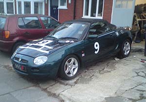
In part 10 of this evolving story of man versus stubborn machine, we saw Project Shed make its triumphant first public appearance at MGF15 at Gaydon, following a flurry of activity nailing the front sub-frame to the car the night before. But there was a problem – and no, I don't mean the mismatched painted panels or the nail in my foot. Ouch. No, “The Problem” was that the rear of the car sat very low to the floor.
Well, some months later, attention has once again centred on getting Project Shed 'ready'. Ready for what exactly, and for when, I don't know. But following yet another significant snow fall, slow and steady progress is once again being made, not only to recondition components going back on the car, but also serious thought invested into the planned modifications – more of which in a moment.
Saggy bottoms
But first – what on earth is going on with the rear suspension? Initial thoughts were that the right rear hydragas sphere had blown – perhaps because the front of the car had been sat with its nose in the air, suspended on axle stands, with the rest of the vehicle's weight resting upon depressurised rear suspension as I tackled the whole replacement/refurbishment of the front sub-frame. As it turns out, this wasn't the case.
I had a chat with Alexander Boucke, a well known hydragas enthusiast with whom I'd been chatting to about an article I wanted to write regarding MGF hydragas suspension (a route that also lead to some enlightening and delightful discussions with Dr Alex Moulton, but that's a tangential excuse for some gratuitous and blatant name dropping). He (Alexander Broucke, not my new friend, Dr Moulton who is a frightfully nice chap don't you know?) wasn't convinced that the hydragas sphere itself was the problem – and he was right. But I don't think either of us would have predicted what the problem actually was. Or rather, were. Pleural.
As it turns out, the driver's side hydragas interconnection was blocked where it reached the rear hydragas unit. Hydragas fluid congeals and crystallizes when it is allowed to dry (guess how I found this out!), and this, in combination with some corrosion, lead to the blockage of the pipe where the bore narrows at the connector. Clearing this took the appliance of a length of copper wire, some thorough dyno-rodding and general ignorance. Then, with the hydragas pump, the system was re-pressurised with the rear Hydragas sphere disconnected. The blockage cleared to the eruption of a stream of sweet-smelling green hydragas fluid. Terrific! So with the rear hydragas unit reconnected, Tim Woolcott and I attempted to re-pressurise the suspension... but something was wrong.
Surprised? No, I didn't think so. Given the fight that Project Shed has mounted so far to being re-commissioned, frankly I wasn't either.
We could not get the pressure above 200psi, and an inspection of the underside of the car revealed hydragas fluid dripping down onto the floor, thus providing the explanation. It was difficult to say from exactly where the leak had sprung, but the off-side pipe was clearly oozing the vital suspension fluid: why it hadn’t leaking before when the rear of the pipe was blocked is anyone's guess, but it now clearly needed replacing. I recalled the vendor's words when we originally collected the striken MGF; one side was on its bump-stops because, he speculated, they'd gone through the interconnection pipe with the trolley jack. But the deflated suspension when we collected project Shed, I recalled, was on the other (off) side. Huh?! So haphazard application of hydraulic lifting tools wasn't the explanation for this leak. To be honest, I've still no idea why this pipe was leaking; these plastic pipes are usually very reliable in service and I can't see of any evidence of the pipe having been damaged.
Pert bottoms
A feeling of dread started to well up as I considered what might possibly be involved in replacing the hydragas pipe. Well, good news on one front – from the donor car I had kept the hydragas pipes, and these were conveniently stored in the in-law's garage. Phew. But would replacing the hydragas pipes, like the brake and clutch hydraulic pipes, necessitate the dropping of the sub-frames? Well, after our previous experiences on that front, I was certainly keen to avoid that sub-frame dropping, bolt shearing scenario. Fortunately, lady luck was in town, as replacing the offside hydragas interconnection pipe turned out to be deceptively simple. Removing the front extension (which encompasses the Schrader valve used to recharge the system) actually meant that it was very easy to thread the pipe up behind the rear of the front sub-frame over the front of the passenger cell bulkhead. Reconnect the front extension, fill the pipe with hydragas fluid, connect up the rear hydragas sphere and pump up... sounds really easy doesn't it? It is. Apart from grubbing under the car, putting the pipe clips back on! Not a recommended job on a car that has no ground clearance because the suspension has not yet been recharged. And then came the moment of truth. Attach up the Liquid Levers Hydragas pump. Time to add some pressure now... 100psi. No leaks. 200Psi. No leaks. 300Psi, suspension starting to rise nicely now, and no leaks. Stopped adding fluid at 380psi because the car now, with its standard Hydragas spheres and knuckle pins bearing down on the upper suspension arms – looked rather uncomfortably like a Land Rover product rather than an MG one due to the ridiculously high ride height – and the lower weight of the car now just exacerbating this look! The time will come to have a look at lowering the car through modification of the hydragas spheres, but that will be once the car is running and when we can get some testing miles in.
Forget bottoms – this is a momentous occasion!
Oh, and I think that there should be a celebration. Did you know that this is the FIRST time, since we picked up Project Shed, that the car has sat perfectly on properly pumped suspension? Oh yes, this was a milestone. It may seem like a relatively trivial and simple job, but both Tim and I felt very pleased with ourselves.
Moving air (not from bottoms)
Having conquered the Hydragas Beast, what could we do next? I knew exactly what I wanted to do next – and that was a modification to the car's aerodynamics that had been intended for the car since we collected it: venting the radiator air through the bonnet.
Those with long memories may recall that in parts 1 and 2, I had cited a few inspirations for Project Shed – those being the MGF Supersports of 1998, the MIRA/MG-Rover MGTF 200HPD 2003 concept and the Vehicle Handling Solutions MGTF Sprint and Hill climb car. The aerodynamic modification I had in mind are to be found on the latter two: both vent their radiator air through the bonnet through a specially fashioned nascel (well, on the VHS Sprint car, it's more of a letter box hole – I hope Andy Kitson won't mind me describing it as such!).
|
|
|
|
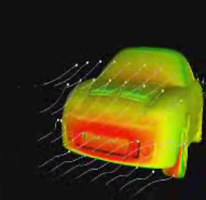
Why on earth would I want to do this? Unfortunately I do not have access to aerodynamic data, but those who were there (unsurprisingly, the MIRA engineers and the VHS chaps, who were then responsible for MGTF development at MG Rover), tell me that this modification reduces lift over the front end to zero, and has the added benefit of reducing aerodynamic drag. All cars develop lift over the front of the car, as there is invariably a low-pressure area, particularly over the front third of the bonnet. The MGF and TF are no different – and perhaps suffer rather more than many of its contemporaries – a problem more noticable because the heavy lump of metal (the engine and gear box) are towards the rear of the car, a location that won't help mitigate the front lift as it might in a more conventional front-engined vehicle. Many MGF owners will report that the steering seems to go light, particularly at speeds of over 50mph. Well, this is why.
Venting the radiator through the bonnet is nothing new. You see it on many sports racers, and a number of sports cars (Lotus Elise for example), as well as a few high performance saloon cars (Japanese 4 wheel drive rally stars like the Mitsubishi Evo springs to mind). And clearly, there is a bit of a precedent for doing this with the MGF/TF too. The key question is to where to place the bonnet vent? Matt Parker has a highly modified MGF, and his bonnet vent is positioned in a very similar place to that used by MIRA – and fair play, the MIRA chaps know what they're doing. But the VHS chaps have made their vent hole rather further back in the bonnet. Why? They know the data, so there must be a reason. So I felt duty bound to investigate this further.
Getting to the bottom of the problem – taking measurements
After some brainstorming with friends on the MGF Register forum, a simple measurement device consisting of some capillary tubes, a piece of card, food dye and duct tape was fashioned together to make a manometer to measure differential air pressure. I even used some sticky back plastic to hold the home-made manometer to the dashboard. How very “Blue Peter” (may I have a badge please?).
|
|
|
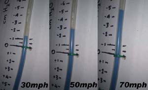
Sticking one end of the pipe on the bonnet, and moving this at 10cm intervals along it, together with the other end of tube at the base of the windscreen and hey voila! I could now map the pressure over the bonnet at 30, 50 and 70mph. 50 road miles later, and I had the data shown below:
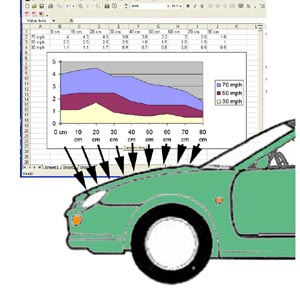
In essence, the negative pressure is at its greatest practically at the leading edge of the bonnet, and extends backwards over the next 30-40cm. There is no positive pressure over the bonnet – at least not significantly, until the base of the windscreen. So if one were to place the bonnet vent at the point of highest negative pressure, one would do so as close to the leading edge of the bonnet as possible (the MIRA solution) – but equally, for convenience's sake, venting the radiator after the bonnet closing panel (30-40cm from the leading edge of the bonnet) should also work well (the VHS solution).
Making holes (insert your own bottom joke here)
With this empirical data
now in my hands, we could plan the first aerodynamic modification to Project
Shed! Oh, and an opportunity to play with Tim's air-saw that he'd just bought
himself. Muhuhuh! Yes, that was fun. The “hot knife through butter” analogy was
clearly developed with this tool in mind – it verily sliced its way through the
steel spare wheel panel. Easy peasy. We cut the spare wheel well panel into two
flaps: a short flap upwards, and a longer flap downwards formed the upper and
lower walls of the newly fashioned radiator duct. Two small sheets of aluminium
were then fashioned to make the sides of the radiator duct. Everything was
painted in smooth black Hammerite, and pop-riveted together. Blimmey! This was
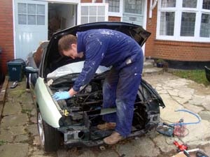
all looking alarmingly professional!!! The next steps are to cut a hole in the
bonnet, and to fashion the back wall of the duct, along with some air direction
flaps, and the job is done.
So, until the next time, Shed watchers, may the wind be with you!
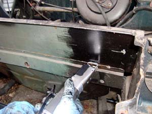
Air saw makes light work of cutting rapidly
through MGF body panels.
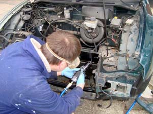
Doctor's air scalpel: making the first
incision!
Here's me making some more delicate
alterations!
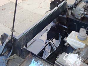
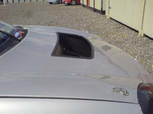
New radiator vent cut through the spare wheel
well
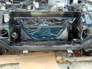
... and here viewed from the front
Masking tape used to rough out where we’re
going to cut the hole in the bonnet for the bonnet vent.