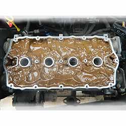
Head Gasket Failure in the MGF and TF is one of the main concerns for owners and prospective buyers alike. Most MGF’s seem to suffer at least one failure, and often, more than that. Head Gasket Failure is not limited the MGF. All K-Series engines, including the KV6 suffer – but none as bad as the rear engine MGF (Ed note: Land Rover Freelander and Lotus Elise are similarly affected. The Elise has a near identical cooling circuit to the MGF, while the Land Rover, while front-engined, is heavy and needs a lot of throttle to get moving - a problem when the engine is cold). To understand the root cause of the failure we should look to the design of the cooling system, we should also think about what features are unique to the F and TF, and any commonality in the individual failures. Firstly I will review the system, and instrument the vehicle as necessary to determine the exact behaviour of the system. Having then identified a potential problem with the system's design, I will show you what I did to mitigate this and then show you the results of the modification and the conclusions that we can draw from these experiments. The MGF Cooling System:
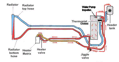
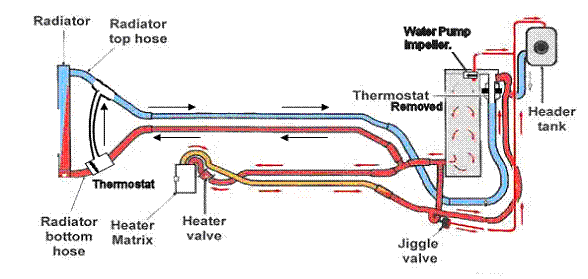
Fig(1): System flow diagram before thermostat opens:
Ignore the narrow pipe running from the jiggle valve to the header tank, and the narrow pipe running from the cylinder head to the header tank – these merely allow air bubbles to disperse and maintain coolant level respectively. They are not involved in the flow. As you can see in the cooling system schematic shown above, the majority of the coolant flow is restricted to the small-volume bypass and heater circuits (the latter only if the heater valve is open). Fig(2): System flow diagram after thermostat opens:
After the thermostat opens, the larger volume radiator circuit comes to play - which is full of cold coolant. At this point, it should be noted that the configuration of the K-Series cooling system is unusual. Normally the thermostat would be located on the ‘outward’ flowing side of the block. It should also be considered, that the volume of cold water in the radiator circuit is far greater than a front-engine vehicle. Interestingly, with the coolant system redesign on the 2003 TF, the Pressure Relief Thermostat (PRT) is relocated to the outward flowing side of the block. Returning to the original
cooling system design, let us consider
the effect of locating the thermostat on the inlet side of the cylinder head, coupled with the high volume of
water in the cooler radiator circuit.
This problem arises because:
All of these factors are easily accounted for in the theory. Due to the location of the thermostat, cold coolant is allowed to surge into the block without being mixed with hot coolant first. The thermostat closes, but because the cylinder head is still hot, the bypass circuit rapidly re-warms to open the thermostat again - thus creating oscillating thermal cycles.
The significant difference here is caused by the location of the thermostat. Compared to conventional engines (e.g. Rover T-Series or O-Series) with the thermostat Located on the outward side of the engine, the cold coolant mixes with the hot bypass coolant before entering the block. Therefore the temperature differentials and variations in these differentials are smaller and so the thermo-mechanical stress is much reduced. There are two further negative effects caused by the thermostat location.
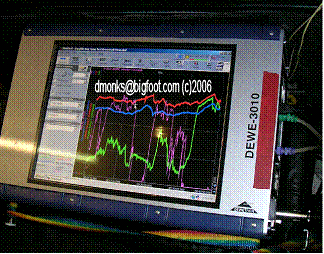
I instrumented my MGF with a Dewetron 3000 Series digital/analogue data logger, 4 thermocouples and a GPS receiver. The following information was logged: 1. Coolant temperature at the thermostat housing – i.e. cooling inlet temperature. 2. Coolant temperature at the outlet elbow. 3. Coolant temperature in the radiator. 5. Engine bay temperature. 6. GPS position – to derive vehicle speed. All experiments were conducted with an outdoor ambient air temperature of +3°C in late December / early January.
The left hand side of the unit consists of 8 + 256 analogue inputs. The four pairs of connections on this panel link to the remotely mounted thermocouple amplifiers. The logger is sat on top of a 200AmpHr YUASA battery to ensure reliable long-term logging.
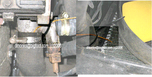
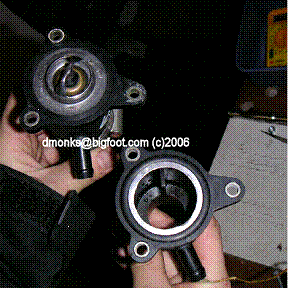
Above: location of thermocouple temperature sensors. Left: in the cylinder head outlet stub pipe (left front corner of the engine) and right: in the radiator itself near return hose.
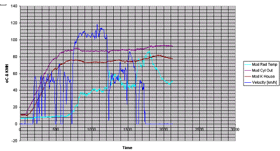
The vehicle was started cold (left overnight). The run starts with some mild town driving, a blast up the motorway, followed by a long run through the countryside. 1hr in total.
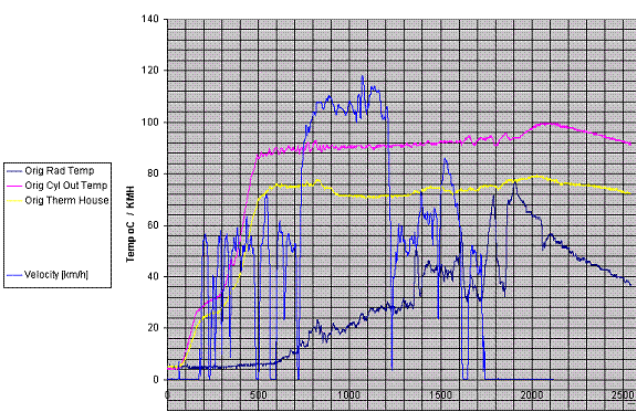
Chart above shows temperature variation (Temp °C) against time (seconds) - time zero being just prior to engine start up. Dark blue: radiator temperature; Magenta: Cylinder head outlet temperature; Yellow: thermostat temperature.
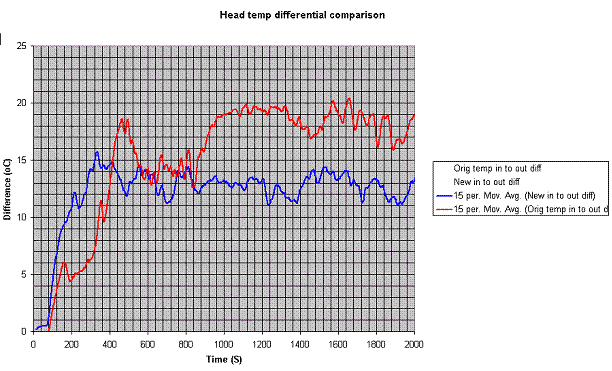
A large differential between inlet temperature and outlet temperature is clear. It is also not a stable differential.
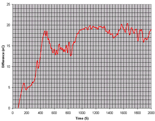
The red line shows the difference in temperature between the inlet and outlet side of the block. The initial climb is expected, but the continual erratic variation that continues will lead to the predicted thermo-mechanical stress. The spike at 500seconds corresponds to a sudden increase in the temperature differential, similar variations follow. The data acquired supports this theory. So now to the solution.
We now know the significant factors that cause the failure:
These two factors must be eliminated. The objective is the relocation of the thermostat and reduction in the volume of cold coolant. Note that this is not a reduction in the volume of coolant, merely are reduction in the volume that is not warmed during the warm up cycle in Fig1 above. The third (and important!) factor – the modification should be affordable! Fig 9 - the proposed modified cooling circuit:
According to the theory, the thermal shock caused by temperature transients across the cylinder head is now minimised, and so the thermo-mechanical shock is also minimised. The setup should now be much less prone to HGF. Practical Application of the Theory: The Remote Thermostat Mod!
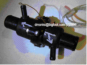
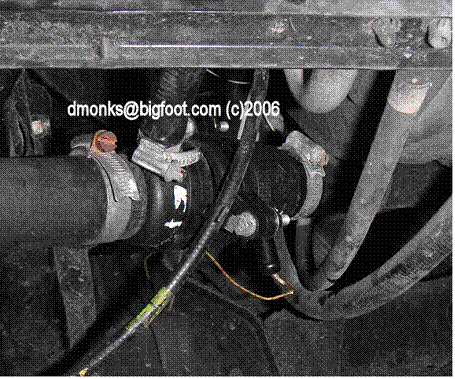
The donors in this case were two Renault Meganes, both equipped with 1.4-litre petrol engines, and both were found in the local scrap yard. Of course, this design leaves a spare ‘bypass’ connection – I used this for a thermocouple to support later data logging – you can just block this off. This design also allows for a smooth laminar flow once the thermostat is open, the bypass tube is fairly large bore – more than adequate for the bypass during the warm up cycle. (Please note: an 8mm thick, hard aluminium ‘gasket’/spacer has been added since this picture – the o-ring alone didn’t make a perfect seal against the second plastic housing.) The remote housing is easily installed on the F – there is even access from above with the plastic bulkhead trim in the wheel well removed. Pictured below from underneath the car:
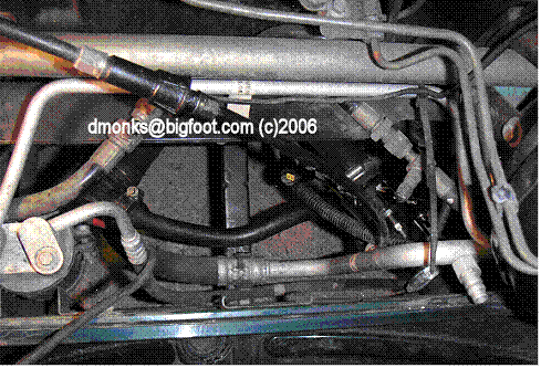
A suitable T-Junction for the bypass circuit was sourced from a scrap Porsche 944, complete with a suitable length of hose. From Above:
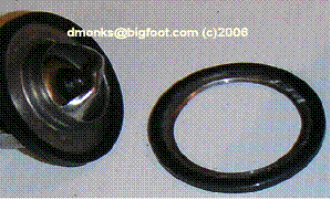
The use of two thermostat housings means a blank ‘washer’ is required to fill the gap between the mounting face of the housing and the recess for the thermostat it originally held. The original MGF thermostat was replaced with a blank in exactly the same way – created by cutting the centre out of a scrap thermostat:
[Ed: you should use the restrictor ring used on post-2003 TFs in the original thermostat housing - the orifice being designed to ensure the appropriate flow/pressure characteristics of the bypass circuit - order from X-Part if needed new, part number PEL000040A] The normal MGF Thermostat is set at 88°C. The new location of the thermostat must be accounted for when deciding which thermostat (operating temperature) to use. To regulate the engine at the same temperature, the temperature drop along the pipe to the new location must be taken into account – this was measured at about 10°C in the previous experiment. A Rover 620Ti thermostat, set at 78°C, is ideal. The T-Series thermostat housing requires a ‘valve’ type thermostat, which closes the bypass when open – the valve plate is easily removed for our application. The results of the Modification The same route was repeated after the modifications had been made. The car was left overnight, to ensure it was completely cold, and the ambient was again about 3°C.
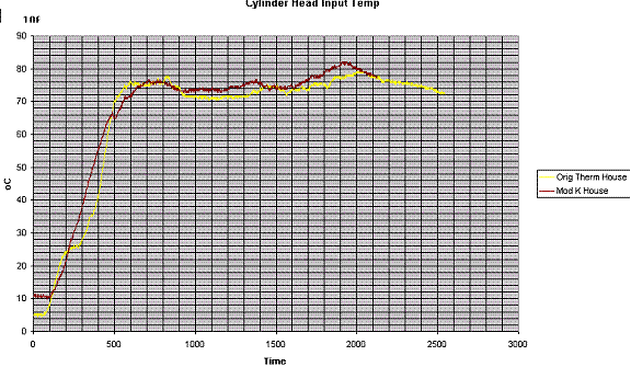
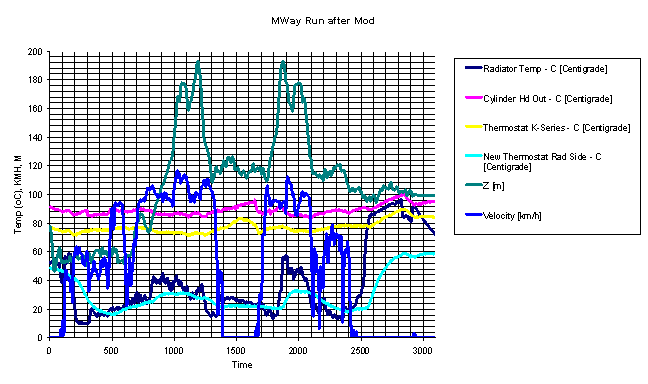
Blue line: Road speed (KMH); Cyan: radiator temperature; Purple: Cylinder head outlet temperature; Burgundy: thermostat housing temperature. It can be seen immediately that the temperature differential across the head is now smaller, and the variations in the differential virtually non existent. The warm up cycle is smoother, and the thermostat only opens once – this time smoothly: it is not forced shut by an in-rush of cold coolant. Comparison pre/post modification Cylinder head input temperature
Yellow: before modification; Red:
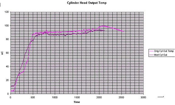
after modification. Cylinder head output temperature
Magenta: before modification;
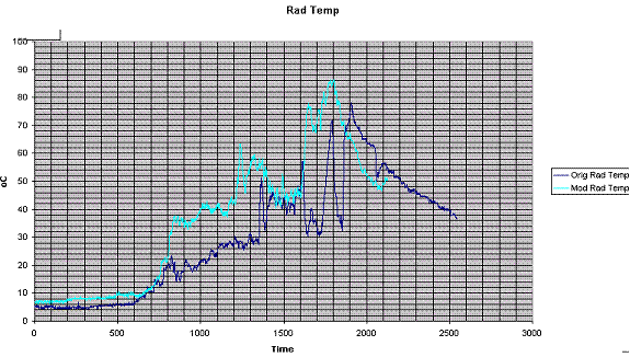
Purple: after modification. Radiator temperature
Dark blue: before modification;
Cyan: after modification. Head temperature differential (inlet/outlet temperatures)
Red: before modification; Blue:
after modification. The difference was clear – and the warm up time was not noticeably affected. An additional test was conducted post modification
This graph shows the various temperatures, speed and now also shows altitude (in dark green). The journey is a return trip along an uphill section of the A3(M) – the return journey can be seen clearly in the symmetry of the altitude vs. time graph. The car was hot at the start of this test, and shows that the new setup is more than capable of regulating engine temperature over a fast uphill struggle. The car was stopped (engine running) for a period of time in the middle (between approximately 1400 - 1675 seconds) – the thermal soak (of approximately 12°C) can be seen on the yellow and pink lines.
This test was conducted post-modification to give confidence that the new cooling system could effectively
regulate the engine temperature under heavy load. The modification has had the desired effect, without any measurable ill side effects. The temperature variations have been minimised and the volume of cold coolant drastically reduced. The cumulative effect of repeat stress cycles will eventually lead to a mechanical failure – be that the wet liner sinking, the head bolts stretching or the water pump failing. With the thermal cycling stress now minimised, HGF should be much less likely.
The theory and results above explain why: the 4mm hole added to the thermostat maintains a continuous flow even whilst the thermostat is closed. The cold coolant in the system is warmed up during the warm up cycle. However, the warm up cycle is extended in this case.
Intuitively you might think they would be first to go. However, the thermostat is removed on these cars to reduce restrictions in the coolant flow to allow better cooling when driven hard – the knock on effect is elimination of the thermal shock experienced by the cylinder head.
Other Causes of HGF It should be noted, that the poor coolant system design is not the only cause of HGF in the MGF.
© David Monks. UK 2006.
Credits and Acknowledgments:
This article has
not been written for financial gain!
|