 |
K&N fitting Instructions Last update: 24/06/03 |
|
K&N fitting Instructions Last update: 24/06/03 |
The instructions below apply for the fitting of the K&N 57i filter kit, although many of the principles are the same for any cone filter. |
Tools required: socket set or spanner (10mm), pair of pliers and a flat head screw driver.
Estimated time for completion: for the first attempt, budget approximately 60 minutes.
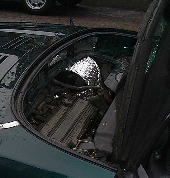
| 1. | With the boot lid open, remove the engine
grill. This is clipped in place along its front (towards front of car) edge. Gently pull
the four clips from the rubber boot seal and lift the assembly clear of the car. View of
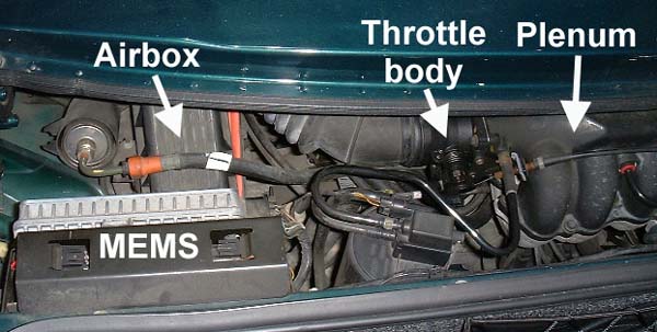
engine bay, standing at rear of car, looking forward: right- oil filler
and dip stick; centre: engine, and closer to you, the plenum chamber [to
which the throttle body is attached]; left: airbox and flexible tube
jubilee clipped to plenum chamber.
|
||
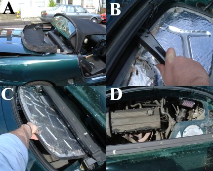
| 2. | Remove engine cover from inside
car. Here's how:
|
||
|
CAUTION: on Mk1 MGFs (pre-2000), there is a sharp edged piece of metal under the rear edge of the T-bar- this will easily graze unwary knuckles! | ||
| 3. |
Undo the jubilee clip at the airbox, and the spring clip on the throttle body, holding the flexible air duct in place. The latter is achieved by using the edge of a flat-bladed screw-driver, and pushing the clip across from one side. Remove the intake ducting (as pictured, opposite). |
||
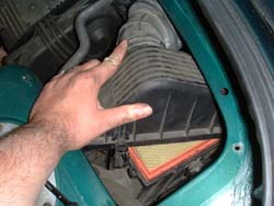
| 4. |
Next, remove the lid of the air filter enclosure. This is achieved by undoing the four retaining spring clips - two at the rear (best viewed through the boot inspection grille) and two on either side at the front of the airbox.
|
||
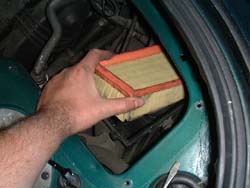
| 5. |
Now remove the original paper element air filter from the air box assembly. |
||
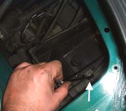
| 6. |
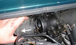
Remove the two retaining screws (should be two, although often only one is to be found!) that hold the airbox to its mounting bracket. A ratchet spanner is particularly useful for this job. IIRC the size is 8mm. Not that there may be other ways in which the airbox is fastened - including plastic retaining pins that can be tugged free. Once the retaining fastenings have been removed, pull the
airbox free.
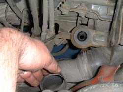
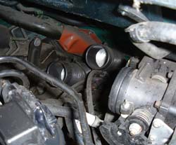
Now peer down into the engine bay, from inside the car looking towards the rear. On the right, near the bottom of the engine bay is a black plastic box. This is the resonance chamber. On its inner surface, there is a rigid elbowed plastic tube pointing upwards towards you, that once lead into the airbox that you have just removed. This needs to be removed to enable you to later thread through the 57i cool air induction tubing. It comes free will a non-too-gentle tug (it won’t damage anything - pictured, opposite). |
||
| 7. |
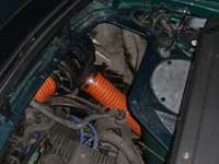
Assemble the filter cone as described in the 57i kit [putting together the cone, a connecting piece and a length of induction tubing]. The induction tube is curved asymmetrically. Make sure the curvature is closest to the cone filter itself. Affix the assembly to the plenum chamber. Tighten the jubilee clips. It is tight enough when it is no longer possible to pull the induction tube off the plenum chamber when attempting to move the attached cone filter back and forth.Click here for the picture of the finished article. |
||
| 8. | Attach the cool air ducts. [UPDATED 4/5/99, 24/6/03] You will need two small cable ties, and SIX large cable ties. (You will need to purchase extra , as the kit only comes supplied with two or three large ties).
|
||
| 9. |
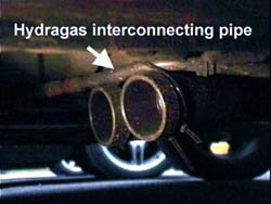
Underneath the car, next to the near side rear wheel, draw the cool air ducts so that the lips of each duct underlie the rear subframe front cross member by pulling/ extending both of the tubes down and forward. Bind the two ducts together with the two large cable ties. Thread the other two large cable ties together at one end. Scrabble under the car, and pass the tie over the top of the cross member and down again so it encircles the cross-member. Present the ends of the two cool air ducts towards the cross-member, and thread the cross-member tie around the cool air duct tie, and fix and tighten together. Trim the excess material. The K&N instructions tell you to connect the K&N cooling ducts to the Hydragas pipes, as shown opposite. Not necessarily a great idea, but it should cause problems. A far more satisfactory solution are Tom Randell's K&N brackets... You do not need ramps to do any of this, so long as you do not mind getting a little dirty! |
||
| 10. | Replace the engine cover, in its correct orientation. Position the hood retaining clips to facilitate the process (as described in step 2, above), and recover the clips above the engine cover plate to allow it to settle in position. | ||
|
DO NOT OVER TIGHTEN THE RETAINING BOLTS: the screw threads are fragile, and the bolts will strip if tightened over enthusiastically. | ||
| 11. | Reposition the sound deadening material and carpet- pay particular attention to that sharp edge under the rear edge of the T-bar. Restore rear aspect of the hood to its original position, and clip back into place. | ||
| 12. | Replace the engine grille from inside the boot. | ||
.... |
Now rev your engine, with a manic grin on your face! Enjoy! |
Budget about 60 minutes for this process. It is quite straight forward, and the difference the filter makes to your car is staggering (but don't just take my words for it!). You will notice greater forward thrust through all the intermediate gears, smoother running, and some people have reported up to 10% increases in fuel economy (shamefully, not something I personally have been able to repeat!). The sound that the filter makes is pure induction noise. It is almost shocking when you hear it for the first time from inside the car. But the greatest plus is that this sound is almost inaudible at a constant cruise. You only get the roar when you want it: when you are putting your foot down!
I have had the 57i kit fitted from there introduction in the early half of 1998, and have not regretted it. I certainly could recommend this product. Happy motoring!
The only mods I've performed to this set up are efforts to improve insulation of the filter from the heat of the engine bay:
CREDITS: Thanks to Andrew Phillips for his help in installing the air filter, and for many of the tips appearing above.
