|
Words & Pictures: Rob Bell |
|
|
Installation of
single-shot
window operation into Mk1 MGF
|
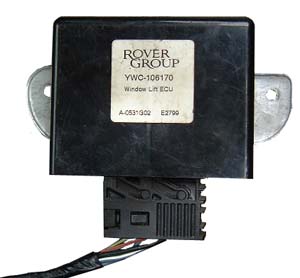
If you have an early (pre-2000 model-year) MGF, you may have wished that your driver's window had a single shot operation - a feature that is particularly useful when you encounter ticket barriers etc. Well, later MGFs and all TFs do have this feature. After Andrew (Scarlet Fever) Phillips suggested purchasing a multi-function unit to see whether this useful window function could be installed into an early MGF, I decided to look into the idea as well. Interestingly, the single shot operation is regulated by a discreet electronic control unit (ECU) - that is usually located in the driver's foot well of cars so equipped.
Looking into the wiring diagrams, the looms of both early and late cars are essentially very similar, apart from this unit, so I arranged the purchase of a window ECU at the same time as Andy. By jove, the thing works brilliantly! In fact, there is no reason why the passenger window shouldn't be single shot as well - although another, separate, ECU would need to be purchased for this purpose.
So you want to install a single-shot window mechanism to your MGF? Read on...
How do you do it?
| You will need: | ||
If you plan to install your window mechanism as a reversible set up, then you'll also need a RH window switch plug, five 5A spade connectors, and 2 male/ 2 female 3A bullet connectors. You will also need to make a mounting bracket to mount your ECU. Where you mount it will largely be dictated by the length of the wiring loom you get with the ECU. |
 |
|
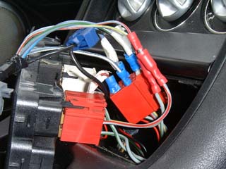
| Reversible installation I made my installation reversible using an extra plug and spade connectors - in the event that I needed to change the wiring connections, but happily this wasn't necessary. See how the spade connectors are slotted into the existing loom plug to establish electrical connection (pictured opposite).
|
 |
|
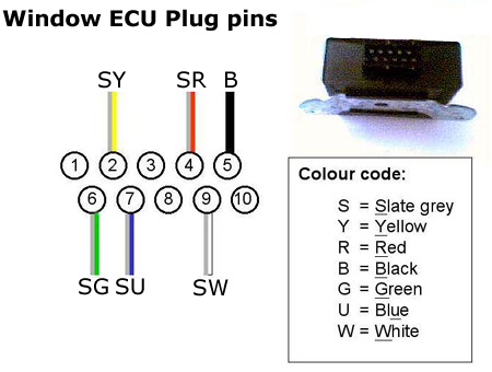
If your ECU has been supplied without a wiring loom plug then your life is made that little more complicated. Unfortunately, obtaining a plug is going to be difficult unless you can salvage one from a scrapped car. To my knowledge, however, the MGF/TF range of cars are the only ones equipped with this particular window lift control module - it really is better to try and obtain one with the ECU if you are buying second hand. However, if you are prepared to wire up your own wiring connections, the diagram opposite shows how to do it... |
||
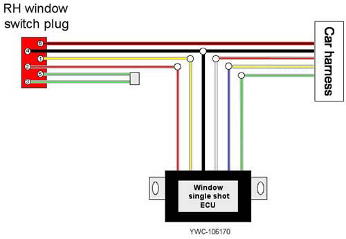
Instructions:
| 1. | Remove the switch panel, and withdraw the plug connector to the RH window switch (red coloured). | |
| 2. | Cut the following wires:
|
|
| 3. | Bare wire ends, and attach to chocolate block connector. | |
| 4. | Take ECU loom, and bare wire ends. | |
| 5. |
Connect the wires to the chocolate block, so that:
Note that the two grey/green wires on the switch
plug (terminals 3 and 5) are now redundant). Note also that in the diagram opposite that
the pin order on the plug is not representative - it's drawn for convenience and clarity. |
Reassemble, and find somewhere to mount the ECU - and job is complete.
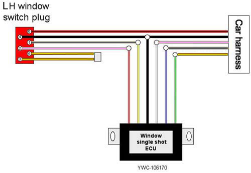
Left hand drive driver's or right hand drive passenger one-shot Window
Clearly, the above instructions are written for the benefit of those of us with right hand drive cars. But what about left hand drive MGFs - or even for those of you who want to have one shot windows on the passenger side? Happily, Thierry Arnault has kindly figured this out for us. Follow instruction steps 1-4, but now skip to instruction step (6) below...
| 6. |
Connect the wires to the chocolate block, so that:
Note that the two brown/ yellow wires on the switch
plug (terminals 3 and 5) are now redundant). Note also that in the diagram opposite that
the pin order on the plug is not representative - it's drawn for convenience and clarity. |