![]()
Interior
Instrument Binnacle Repair
|
Words and Pictures: Rob Bell |
|
|
Common Problems Instrument Binnacle Repair
|
 Here's the problem illustrated - a large gap is evident between the dashboard and the binnacle. This flaps about over rough roads - and is extremely irritating! |
As plastic ages, it gets brittle - and that is the underlying problem for this increasingly common problem on MGFs - failure of the instrument binnacle cowl brackets. There are three, spaced equally around the outer circumference of the rear of the binnacle. Failure is undoubtedly a multifactorial process - possibly related to scuttle shake and vibrations leading to fatigue failure, or perhaps a mechanic has been a little too heavy handed during some repair or other. But if the brackets have broken, you soon get to know about it: the back of the binnacle flaps about, and this can lead to the whole instrument pack vibrating manically over rough roads, as it is affixed along its top edge to the top of the binnacle - as we shall see.
Repairing the brackets, which are a moulded part of the instrument binnacle cowl, ought to be something that is easy to fix - but surprisingly, the instrument cowl is not available as a separate part from MG. Indeed, it appears that the cowl is attached to the fascia before the air ducts are bonded to the underside of the dashboard: the self tapping screws are attached from behind - so even with the instrument pack removed, it is still not possible to easily remove the brackets. So how do you repair the brackets? The most obvious solution is to glue them together - but choose your adhesive wisely. For example, on my car, the brackets had been glued back together at some point using what appears to be superglue. It's hopeless: the joints rapidly fractured again, and the result is a horrible mess. Superglue, and adhesives like it, simply aren't flexible enough in this environment. Also bear in mind that the area under the windscreen can be a very harsh environment - a mini-green house effect. And as we're also talking about a convertible, it can be a pretty humid environment as well... In the end, I decided to use two-pack epoxy resin to reattach the brackets to the cowl - a solution that I hope will be permanent. Time will tell, and I shall add my experiences here!
Tools Required
|
Materials Required
|
Time Required
|
Instructions
![]() Ensure that you have your radio codes recorded and
then disconnect the battery before commencing work.
Ensure that you have your radio codes recorded and
then disconnect the battery before commencing work.
| 1. |
 The
first task is to remove the steering column cover. It is in two parts,
clipped together - but before separating, the lower half of the trim needs
to be unscrewed from the column - there are three screws in total. The
first task is to remove the steering column cover. It is in two parts,
clipped together - but before separating, the lower half of the trim needs
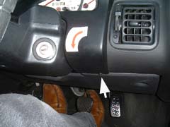
to be unscrewed from the column - there are three screws in total.In this first picture, we can see the two screws under the steering column. Remove both Phillips-head screws. |
 The
third screw is hidden away - so the next step is to drop the fuse box cover.
This is held in place by two plastic screws. A coin is suitable for undoing
these - a quarter to half a turn is enough to release. Once both have been
turned, the lid will simple flop down. The
third screw is hidden away - so the next step is to drop the fuse box cover.
This is held in place by two plastic screws. A coin is suitable for undoing
these - a quarter to half a turn is enough to release. Once both have been
turned, the lid will simple flop down.
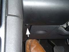
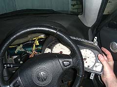
This will expose the third steering column trim screw - pictured right. Again, Phillips-headed, remove screw, and put all three screws together in a safe place. |
|
| 2. |
 Now
we can start to tackle the instrument cowl. The front cowl trim needs to be
removed
first. There are four screws - two in the upper section
of the trim, pictured right, and one either side of the steering column, as
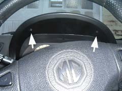
shown below. Now
we can start to tackle the instrument cowl. The front cowl trim needs to be
removed
first. There are four screws - two in the upper section
of the trim, pictured right, and one either side of the steering column, as
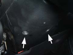
shown below.Remove the screws, and put them in a safe place. The trim can now be tilted forward and withdrawn, exposing the instrument binnacle mounting.
|
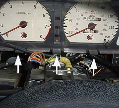
| 3. |
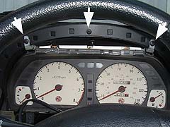 The
instrument binnacle is mounted very simply to the binnacle cowl at the top,
and to the dashboard supports on the bottom corners. The upper mounting
screws are shown to the right (ignore the middle arrow - this is pointing to
one of the instrument pack mounting bracket retaining screws). The
instrument binnacle is mounted very simply to the binnacle cowl at the top,
and to the dashboard supports on the bottom corners. The upper mounting
screws are shown to the right (ignore the middle arrow - this is pointing to
one of the instrument pack mounting bracket retaining screws). |
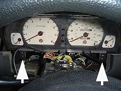 And
the lower instrument retaining screws are shown here. Remove all four
screws, and keep in a safe place. And
the lower instrument retaining screws are shown here. Remove all four
screws, and keep in a safe place. |
|
| 4. |
 The
next step is to remove the instrument pack - which is a step that isn't immediately
obvious as to how achieved. There are three connector blocks entering into the rear of the
instrument pack - two at the top and one in the middle of the instrument pack,
between the two main dials. In addition, on early MGFs like mine, which use
a mechanical speedometer, there is a cable drive to the back of the
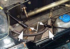
instrument. The
next step is to remove the instrument pack - which is a step that isn't immediately
obvious as to how achieved. There are three connector blocks entering into the rear of the
instrument pack - two at the top and one in the middle of the instrument pack,
between the two main dials. In addition, on early MGFs like mine, which use
a mechanical speedometer, there is a cable drive to the back of the
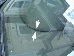
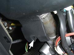
instrument.Unfortunately, it is almost impossible to get your hand behind the instruments to access these connectors - but I got this useful tip from Andy 'Scarlet Fever' Phillips - he suggested separating the speedo cable before it enters the cabin, in front of the main bulk head - as shown pictured right. You need to remove the bulkhead shroud first though, which is covered elsewhere. You can then push the cable into the cabin which creates sufficient slack to tilt the instrument pack forward so you can get your hands behind the instrument to disconnect the plugs and the speedo drive from the instrument pack... |
| 5. |
 With
the cables and harness plugs removed, it is now possible to remove the
instrument pack from the dashboard - do this by tilting the 'pack and
withdrawing to one side - as shown right. With
the cables and harness plugs removed, it is now possible to remove the
instrument pack from the dashboard - do this by tilting the 'pack and
withdrawing to one side - as shown right. |
| 6. |
 It is
now possible to see the rear of the instrument pack for the first time!
Shown with red arrows are the locations of the three connectors that need to
be removed, along with the speedo drive that needs to be unscrewed. All
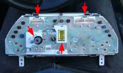
pretty straight forward stuff. It is
now possible to see the rear of the instrument pack for the first time!
Shown with red arrows are the locations of the three connectors that need to
be removed, along with the speedo drive that needs to be unscrewed. All
pretty straight forward stuff.If you want to use Brown and Gammons low-coolant-level warning system and employ one of the redundant warning bulbs, now's the time! The catalyst over heat lamp is not included on the printed circuit on the rear of the instrument pack - and uses a separate bulb-holder. Perfect! This is what I've had done... |
| 7. |
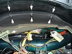 With the
instrument pack out of the way, we can now see the problem. Here, on my car,
all three plastic brackets can be seen, and all three have snapped! At the
bottom of the image, you can also see all the cables that we've disconnected
from the instrument pack... With the
instrument pack out of the way, we can now see the problem. Here, on my car,
all three plastic brackets can be seen, and all three have snapped! At the
bottom of the image, you can also see all the cables that we've disconnected
from the instrument pack... |
| 8. | Now's the time
to apply your adhesive of choice. As mentioned earlier, I used a two pack
epoxy resin. I applied it liberally to both surfaces, and then pressed down
on the rear of the instrument cowl to ensure that the two sides bonded
together successfully and in the correct place. You can use a number of
heavy weights to do this (I grabbed a sturdy torque wrench, but I guess a
sand bag would be better!) Allow the adhesive to cure fully before reassembly - depending on what you decide to use, this can take up to 24 hours - so bear this in mind when planning to undertake this work! |
| 9. |
 Reassembly time!
And yes, in true Haynes manual tradition, we're talking about the reverse of
the disassembly instructions!!! Reassembly time!
And yes, in true Haynes manual tradition, we're talking about the reverse of
the disassembly instructions!!!
The main hint here, as provided by Tony, is to ensure that the rubber anti-rattle bushes are retained on the tabs at the base of the instrument pack - there are three along the base of the instrument pack. When reassembling, make sure that all three are still there - and that you've not accidentally lost one in the foot well during the rebuild process. With that, it is hopefully job done - but do make sure you've remember to reconnect all three loom plugs and the speedo cable to the back of the instrument, and the speedo cable under the bonnet before driving off only to discover that something is not working. With luck, you've now sorted this very annoying problem!!! |