|
Words and pictures: Rob Bell |
|
|
The MGF/TF Heater Box: how
does it work?
|
Introduction
|
|
The MGF/TF heater has an excellent reputation for prodigious heat output and reliability - two things that are essential on an open-top roadster. Given that it goes about its business so unobtrusively and is so tucked away, you may never have paid it a second thought. For those of you more curious as to the inner workings of the heater, this page is for you - and highlights the two main problems that may occur with these heater units: debris accumulation and failure of the heater fan speed-speed controller.
Contents:
Location of the heater
External anatomy of the heater box
Common
problems: debris
Common
problems: failure of resistor pack and loss of fan speeds 1, 2 and 3
Internal anatomy of the heater box
Airflow
through the heater box
Airflow
distribution
|
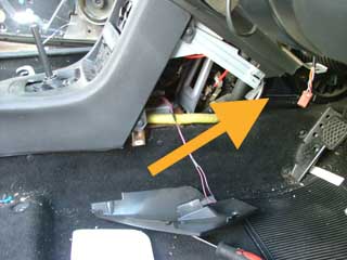
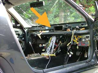
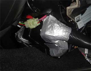
Location of the heater The location of the heater box on the MGF and TF is not that usual: like that found on most cars, it is hidden well away behind the dashboard. I suspect that it was one of the first components to be installed in the car on the assembly line - and as a result, the rest of the interior is assembled around it - a point well illustrated in the image opposite, right (heater box is arrowed here - and only the central high-level air feed duct is visible; the bulk of the heater is buried below). To remove the heater unit requires extensive disassembly of the interior including the removal of the dashboard - fortunately this is not too difficult to do, but as one can imagine, it is quite a substantial job given the amount of trim and other assembly removal required to get at the heater box! |
 |
|
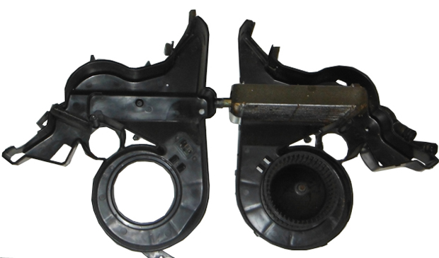
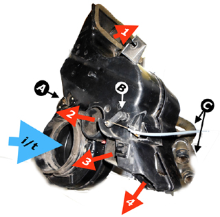
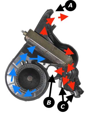
The External Anatomy of the heater box Once removed, one can almost immediately get a feel as to how this surprisingly simple component works: it is essentially a large plastic box that contains a motor, a water radiator and an air distribution flap! In the figure opposite, right, A reveals the location of the fan-speed resistor pack. B is the air distribution flap lever arm and C represents to the coolant pipes from the engine. Air flow is indicated by the arrows: the blue arrow labelled "i/t" is the air intake from the scuttle-mounted air intake plenum, that takes it's air intake from the base of the windscreen on the passenger side. The red arrows are where the warmed air exits the heater box: 1 - the fascia level air vents; 2 - the windscreen demister vents and 3 & 4 the foot well air exits. |
 |
|
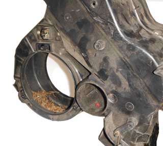
Common Problems: debris in heater box One of the two common problems to affect the heater is the accumulation of debris - typically dry leaves and other decaying vegetable material - which rattles away when the fan is at speed - and occasionally spewing this into the passenger compartment! To clear this will require some disassembly - assess from the passenger foot well and removal of the air intake trunking will enable limited access with a vacuum cleaner - but ideally, removal of the heater motor is required (held in by three large self-tapping screws), which can only be accessed from the limited confines of the driver foot well... tricky! |
 |
|
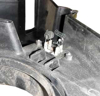
Common Problems: burnt out resistor coils Loss of fan speeds 1, 2 and less commonly 3 usually points to the failure of the resistor pack, which is attached to the air-box. The speed is reduced by increasing resistance in series from 3 to 2 to 1 setting. Each resistor is little more than a coiled length resistor wire, which is cooled by the air flow generated by the heater fan. Annoyingly, the higher the resistance, the greater the heat in the resistor, and the slower the fan speed, the less cooling the resistor coils get. Unsurprisingly they can burn out over time. A replacement coil pack is available, but so are replacement resistors that you can solder on yourself for considerably less! |
 |
|
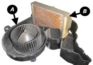
The internal anatomy of the heater box Here's the inside of the heater box assembly that you may not have seen previously. Essentially, it is a large plastic casing containing three basic components:
|
|
|
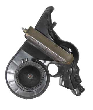
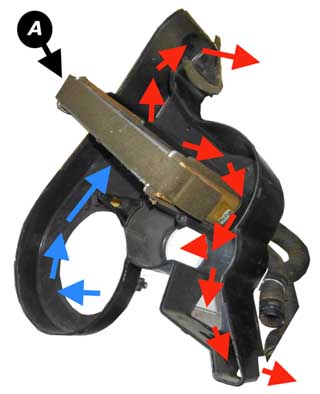
Airflow through the heater box Cold air is drawn into the motor casing, and centripetally pushed out through a snail-like air box (blue arrows) through the radiator, where is picks up heat and then is distributed to the various outlets in the heater box.
|
 |
| Picture opposite here shows the same as above, but from another angle (very arty!) - the radiator (or heat exchanger) is labelled (A) here in the picture opposite right. |
 |
|
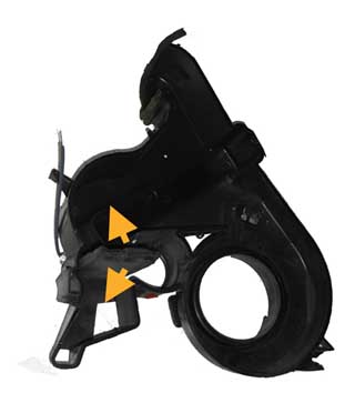
Air flow distribution As mentioned above, the air flow through the heater box, is controlled by a simple flap that can be moved either up or down (yellow arrows) to force air only through the fascia vents, through the demister or through the footwell outlets. What I think can be quickly surmised is that the airflow will always be via the fascia vents unless these have been individually closed off - and in fact the flow is preferentially to the fascia vents by the design of the airbox. With the flap in an intermediate position, the airflow has an opportunity to flow through all outlets, although flow will preferentially be via exits of least resistance - usually the fascia vents and the foot well vents. With the flap in the lower-most position, airflow will be via the fascia vents and demister outlet. You've probably already noticed that to get the best windscreen demisting you need to close the fascia vents - and this is why! |
 |
Conclusion
  |
The MG's heater box is extremely simple, rugged and reliable. The only real problem to beset this unit is failure of the heater fan speed controller resistors - and this can be fixed for pennies if you have even rudimentary soldering skills!
I have not covered air conditioning here - a very rare option in the UK - but the heater remains unaltered in this application; the air-conditioning unit instead sits 'upstream' of the heater unit and supplies chilled air for distribution via the standard heater box assembly.
One interesting modification to consider is the "Air Scarf" - achieved by running some ducting from the foot well vents to the headrest area of the seat - a modification that is explained in more detail by the idea's originator, Leigh Ping, elsewhere (the T-Bar forum link).
Hope this has been of interest!