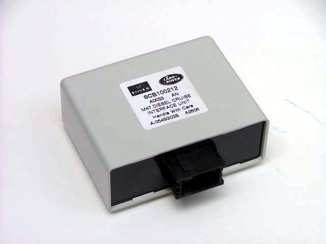
 Component
parts first: cruise control interface
Component
parts first: cruise control interface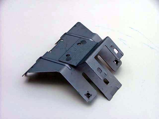 Cruise
interface mounting bracket
Cruise
interface mounting bracket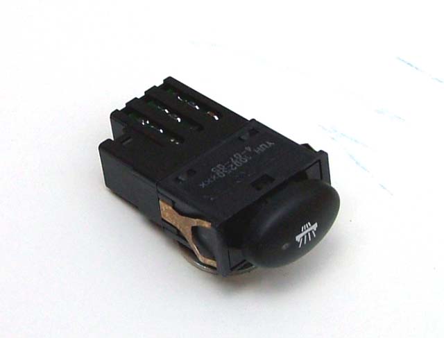 Cruise
control master switch
Cruise
control master switch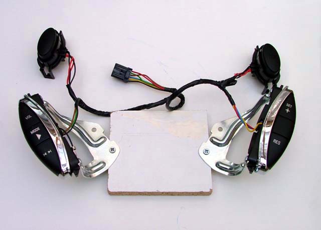 Steering
wheel switches (note that the cruise control switches come with replacement
horns and ICE control switches...)
Steering
wheel switches (note that the cruise control switches come with replacement
horns and ICE control switches...)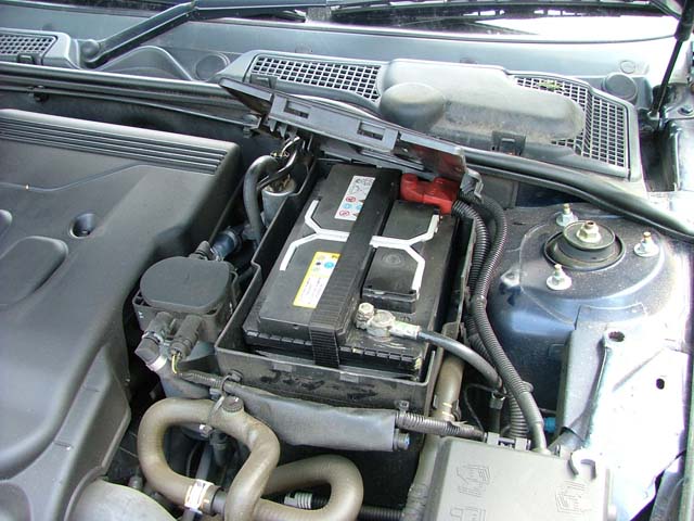 First
step - disconnect the battery!
First
step - disconnect the battery!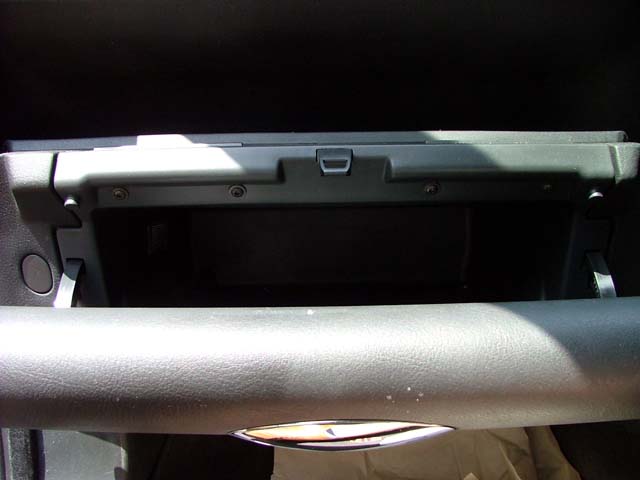 Next,
open the glove box...
Next,
open the glove box...... and remove the retaining screws in along its top face (visible in picture opposite).
 There
are three screws to expose - one in each corner (as shown here), and one in
the centre.
There
are three screws to expose - one in each corner (as shown here), and one in
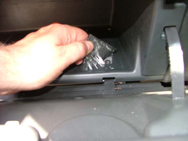
the centre.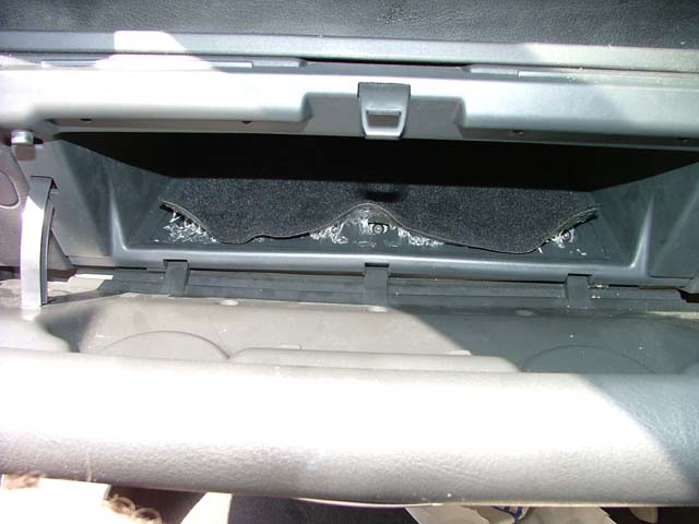 This
is what it will look like after peeling back the carpet - it comes up with
finger nails...
This
is what it will look like after peeling back the carpet - it comes up with
finger nails...Now undo all three screws (unhelpfully, these are star bits - you may need to expand your tool selection here). The glove box will now just pull out...
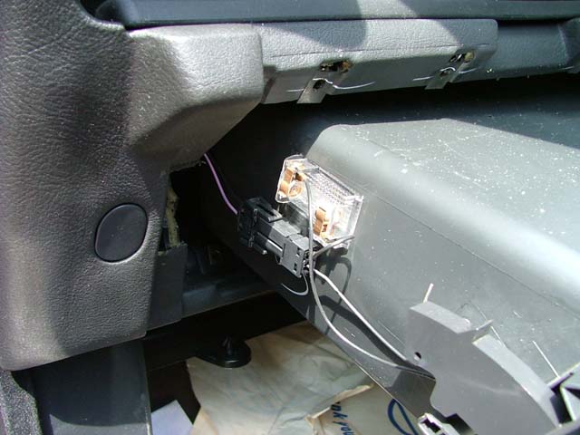 But
before removing completely, disconnect the glove box lamp.
But
before removing completely, disconnect the glove box lamp.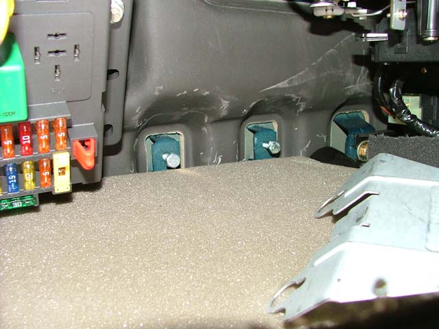 Next,
I screwed in the two cruise interface bracket retaining bolts in the front
bulkhead - located to the right of the fuse box.
Next,
I screwed in the two cruise interface bracket retaining bolts in the front
bulkhead - located to the right of the fuse box.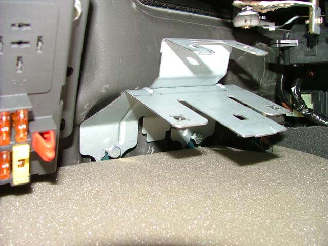 The
bracket slots on...
The
bracket slots on...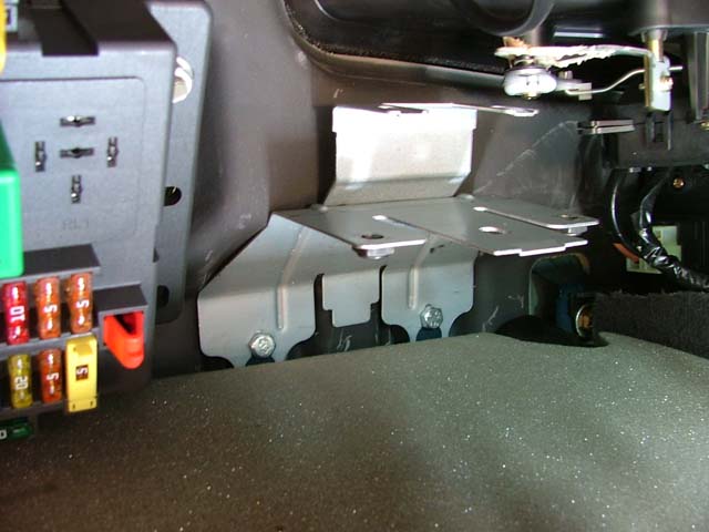 And
now tighten the bolts - and the bracket is held securely in place.
And
now tighten the bolts - and the bracket is held securely in place.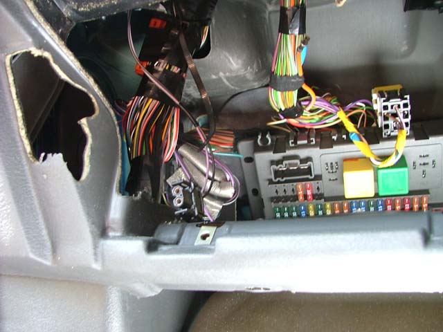 Now
look for the cruise control wiring loom - it should be taped up with the
main loom cables. This is where the wheels came of the wagon for me -it was no where to be found!
Now
look for the cruise control wiring loom - it should be taped up with the
main loom cables. This is where the wheels came of the wagon for me -it was no where to be found!
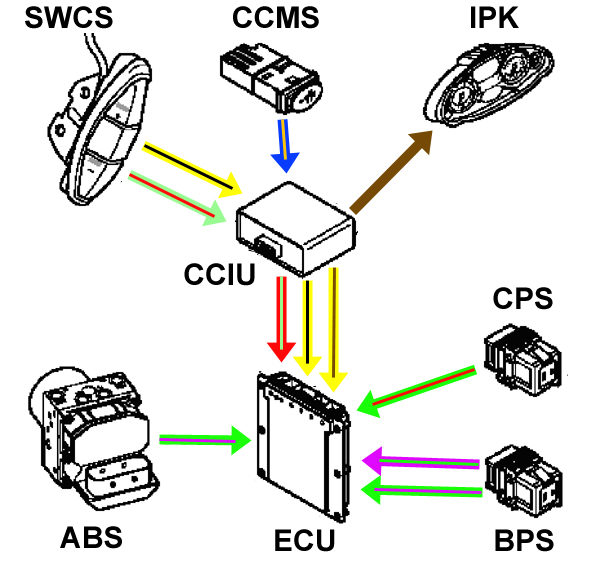
To enable identification, the connector in question is rectangular and black. The
wires coming out of it are predominantly yellow! See detail below (the
second colour statement in italics - where stated - is the wire's tracer
colour):
Cruise interface unit (connector #C0895; 12-pin
rectangular black plastic female connector, 2x6 pins): Black, Red/light
green, Light green/red, Yellow/black (x2), Yellow/brown,
Yellow/black, blue/orange, Yellow/blue, and Brown (in
pins 1 to 9 respectively).
 To
confirm the absence of the cruise control loom, I next turned my attention
to the centre console. First I removed the trim panel (notice that my car
has no optional switches here - which appears to predict the absence of the
loom...)
To
confirm the absence of the cruise control loom, I next turned my attention
to the centre console. First I removed the trim panel (notice that my car
has no optional switches here - which appears to predict the absence of the
loom...)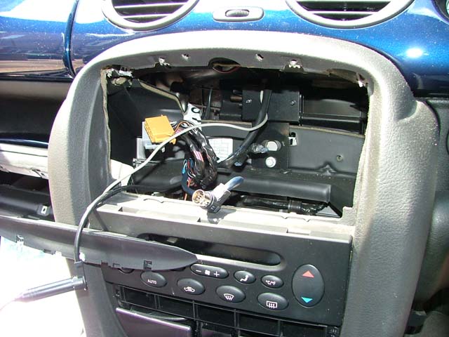 Next,
to make things easier to find the wiring loom - if present - I removed the
in car entertainment system.
Next,
to make things easier to find the wiring loom - if present - I removed the
in car entertainment system.Note that there is plenty of space back there to fit a double DIN head unit... something I am rather tempted to do in the future!
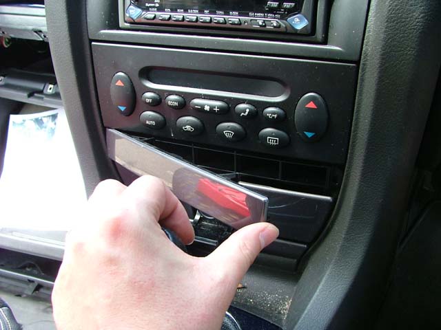
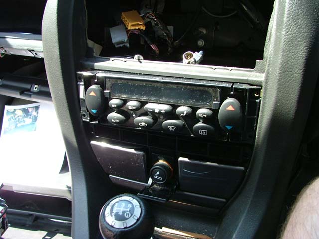 Now
remove the automatic climate control unit (ATC). Prise the fascia plate off
using the edge of a credit card or similar. This exposes four philips
screws. Undo these and the ATC pulls free.
Now
remove the automatic climate control unit (ATC). Prise the fascia plate off
using the edge of a credit card or similar. This exposes four philips
screws. Undo these and the ATC pulls free.There are a couple of wiring connections that need disconnecting before removing completely. Straightforward stuff.
The switch panel below simply unclips and pulls free.
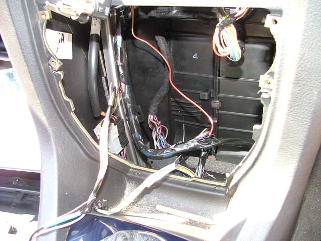 I
also went to the trouble of removing the ashtray/ drink holder unit below
this (for installing cruise control, this is not necessary).
I
also went to the trouble of removing the ashtray/ drink holder unit below
this (for installing cruise control, this is not necessary).But doing so does reveal an interesting area of dashboard that you never usually see. And I could see no evidence of a cruise control loom!!! So I need to source one. The quest continues...
If there are switches taped up back there, the wire codes for the connector are as below (colour in italics is the wire's tracer colour):
Master switch (S124) (connector #C0749 black plastic; 6-pin female connector 2x3 pins): Black, Blue/orange, White/ blue plus instrument illumination - Red/white.
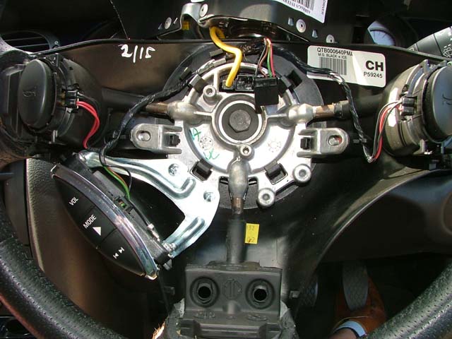 For
completeness sake, I also removed the airbag from the steering wheel. This
is inside the standard MG ZT steering wheel. Holes are already there for the
retaining self-tappers for the cruise switches. A slot needs to be cut in
the backing trim of the steering wheel boss to take the new switch though.
For
completeness sake, I also removed the airbag from the steering wheel. This
is inside the standard MG ZT steering wheel. Holes are already there for the
retaining self-tappers for the cruise switches. A slot needs to be cut in
the backing trim of the steering wheel boss to take the new switch though.
Take a template from the ICE switch aperture, and transfer this to the other side, and the job's a good 'un! No need to source a cruise-equipped steering wheel.
The wires in the steering column should be (colour in italics is the wire's tracer colour):
Steering column switch (rotary coupler, connector #C0082): Light green/red, Yellow/black (plus the standard wires for horn and ICE control).